Eureka AIR delivers breakthrough ideas for toughest innovation challenges, trusted by R&D personnel around the world.

Stapler with a moveable staple pressing mechanism

Inactive Publication Date: 2018-01-18
SDI CORPORATION
View PDF6 Cites 1 Cited by
  • Summary
  • Abstract
  • Description
  • Claims
  • Application Information

AI Technical Summary

Benefits of technology

The present invention is a stapler with a movable staple pressing mechanism. The main purpose of this patent is to provide a stapler that can handle different types of staples without difficulty in stapling, and to reduce poor stapling. When using this stapler, the staple pressing base can be pressed downward to securely hold the staples in place without any movement. When the user finishes stapling and releases the trigger lever, the staple pressing base remains in place, preventing any space between the staples and the base. This prevents the staples from rotating or moving upward. When the stapler is moved back to its original position, the staple pressing base also moves back to its original position, restoring the stapler to its original state. This stapler with a movable staple pressing mechanism can improve the quality of stapling and makes it easier to use with different types of staples.

Problems solved by technology

Therefore, poor stapling easily occurs.

Method used


Image

  • Stapler with a moveable staple pressing mechanism
  • Stapler with a moveable staple pressing mechanism
  • Stapler with a moveable staple pressing mechanism

Examples


Embodiment Construction

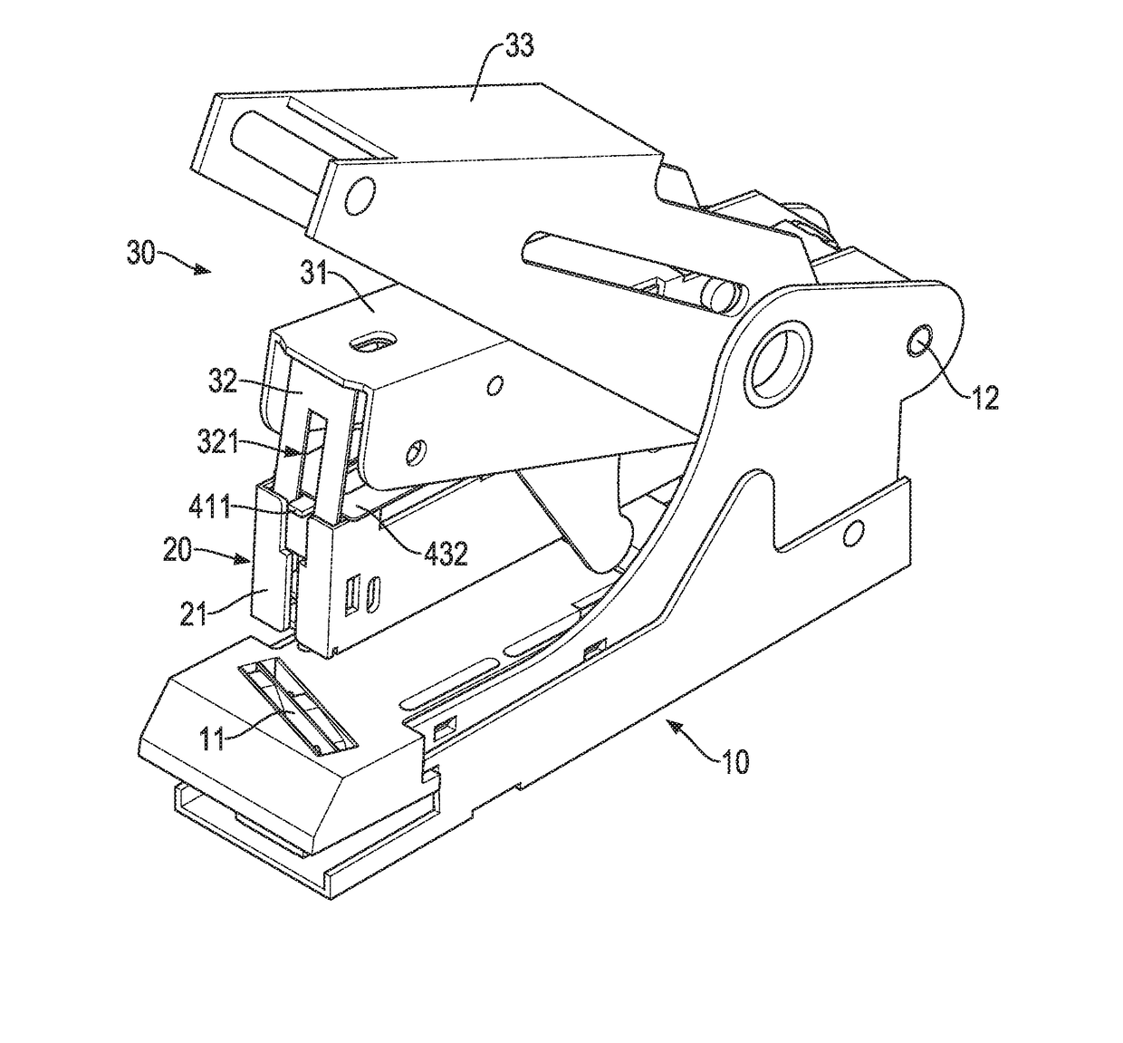
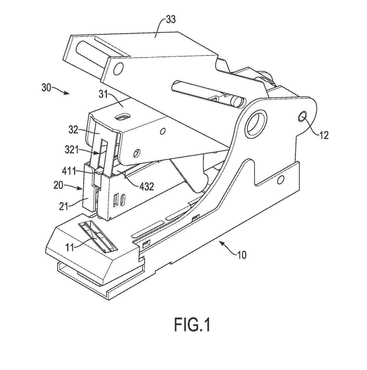
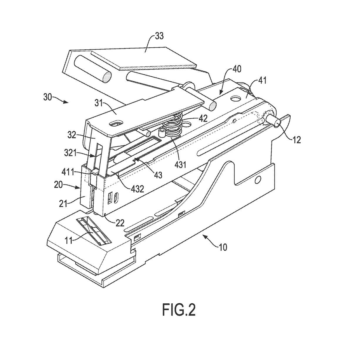
[0022]With reference to FIGS. 1 to 4, a first embodiment of a stapler with a movable staple pressing mechanism in accordance with the present invention comprises a base 10, a magazine assembly 20, an arm assembly 30, and a staple pressing mechanism 40. The base 10 comprises an anvil structure 11 disposed on a front end of the base 10. A pivot unit 12 is mounted on a rear end of the magazine assembly 20 and a rear end of the base 10, such that the magazine assembly 20 is pivoted on the base 10 by the pivot unit 12. The magazine assembly 20 comprises a magazine 21. A staple opening 22 is formed on a bottom of a front end of the magazine 21, and a position of the staple opening 22 corresponds to that of the anvil structure 11.

[0023]The arm assembly 30 is located above the magazine assembly 20, and a rear end of the arm assembly 30 is pivoted on the rear end of the base 10 by the pivot unit 12. The arm assembly 30 comprises a trigger lever 31 pivoted on the base 10 by a rear end of the ...


PUM


Abstract

A stapler with a movable staple pressing mechanism has a base, a magazine assembly, an arm assembly, and a staple pressing mechanism. The magazine assembly is pivoted on the base and has a magazine. The arm assembly is pivoted on the base, is located above the magazine assembly, and has a trigger lever and a staple pressing tab. The staple pressing mechanism is mounted between the magazine assembly and the arm assembly, and has a staple pressing base, a trigger elastic unit, and a restoring elastic unit. The staple pressing base is pivoted on the base and located in the magazine. The trigger elastic unit is mounted between the trigger lever and the staple pressing base. The restoring elastic unit is mounted between the arm assembly and the magazine assembly to provide a restoring elastic force for the staple pressing base.

Description

BACKGROUND OF THE INVENTION1. Field of the Invention[0001]The present invention relates to a stapler, and more particularly to a stapler with a moveable staple pressing mechanism.2. Description of Related Art[0002]When a conventional stapler is stapling, a user presses a trigger lever to press downwardly a staple pressing tab to press staples. A forefront staple placed in a magazine of the conventional stapler is separated from the remaining staples and is pressed toward a staple opening of the magazine by the staple pressing tab, and legs of the staple that is pressed out of the staple opening are bent on an anvil. Staples that are left in the conventional stapler are pushed forwards by a staple pushing unit to fill a vacancy of the staple that is pressed out of the staple opening, such that a stapling process is finished.[0003]Partial structures and operational processes of a conventional large stapler 60 are shown in FIGS. 10 and 11. A magazine 61 of the conventional large staple...

Claims


Application Information

Patent Timeline
IPC IPC(8): B25C5/02
CPCB25C5/025
Inventor CHEN, CHING-LI
Owner SDI CORPORATION
Why Eureka
Eureka Blog
Learn More