Printing Apparatus and Method for Removing Contaminants In Printing Apparatus

Active Publication Date: 2017-06-15
SEIKO EPSON CORP
View PDF1 Cites 0 Cited by
  • Summary
  • Abstract
  • Description
  • Claims
  • Application Information

AI Technical Summary

Benefits of technology

This patent describes a printing machine that prevents contaminants from sticking to the paper and causing poor printing. This is achieved by designing a housing unit that comes into contact with a contact portion, removing any contaminants attached to the housing unit. This design also prevents damage to the contact portion during cutting blades cutting, and reduces the likelihood of shape changes to the contact portion. Overall, this patent describes a way to improve the printing quality of a printing machine.

Problems solved by technology

However, in the above-mentioned image forming device there is a problem in that, because it does not have a function of cleaning a housing unit, contaminants which become attached to the housing unit at the time of the movement of the transcript material cutting apparatus become scattered and the scattered contaminants attach to a recording head which results in the occurrence of poor printing.

Method used


Image

  • Printing Apparatus and Method for Removing Contaminants In Printing Apparatus
  • Printing Apparatus and Method for Removing Contaminants In Printing Apparatus
  • Printing Apparatus and Method for Removing Contaminants In Printing Apparatus

Examples


modification example 1

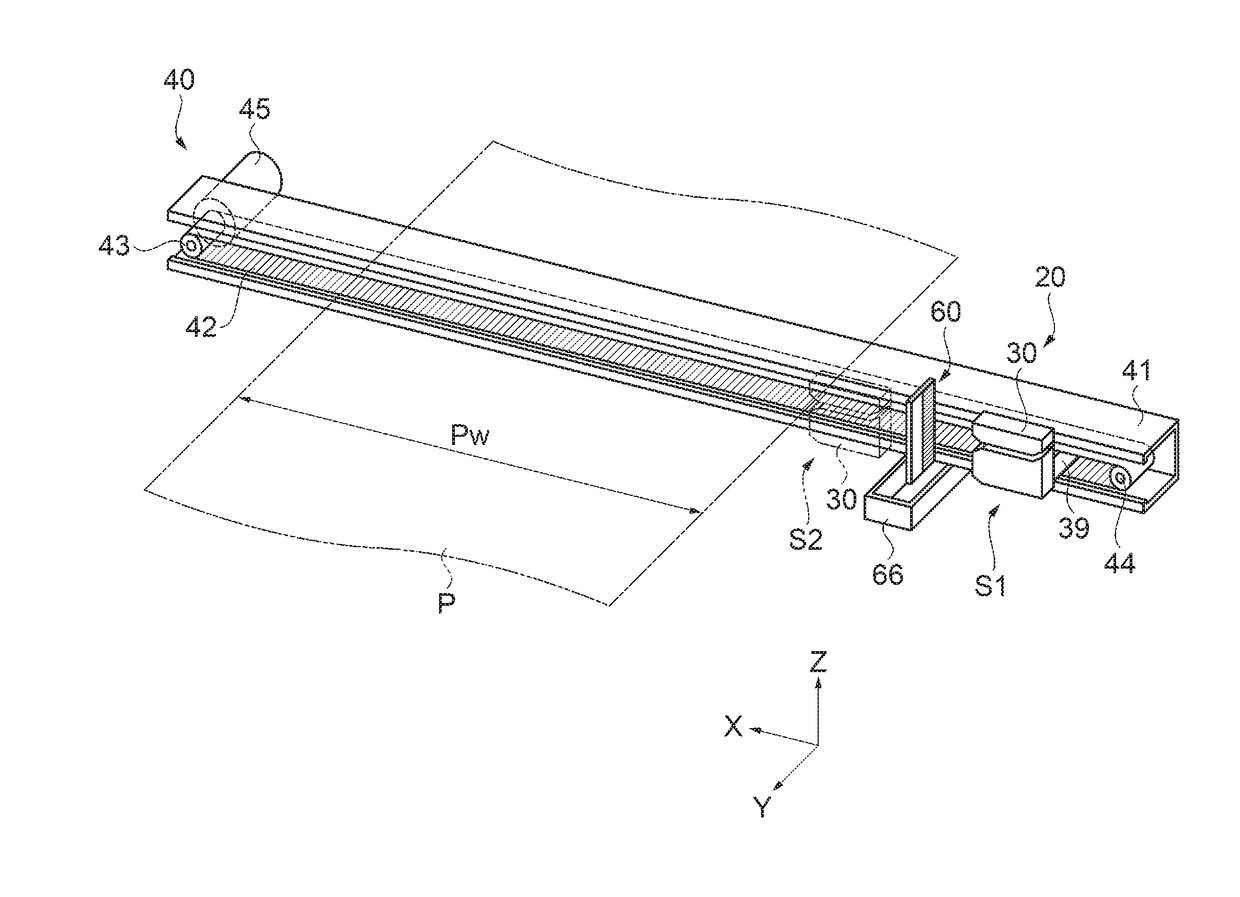
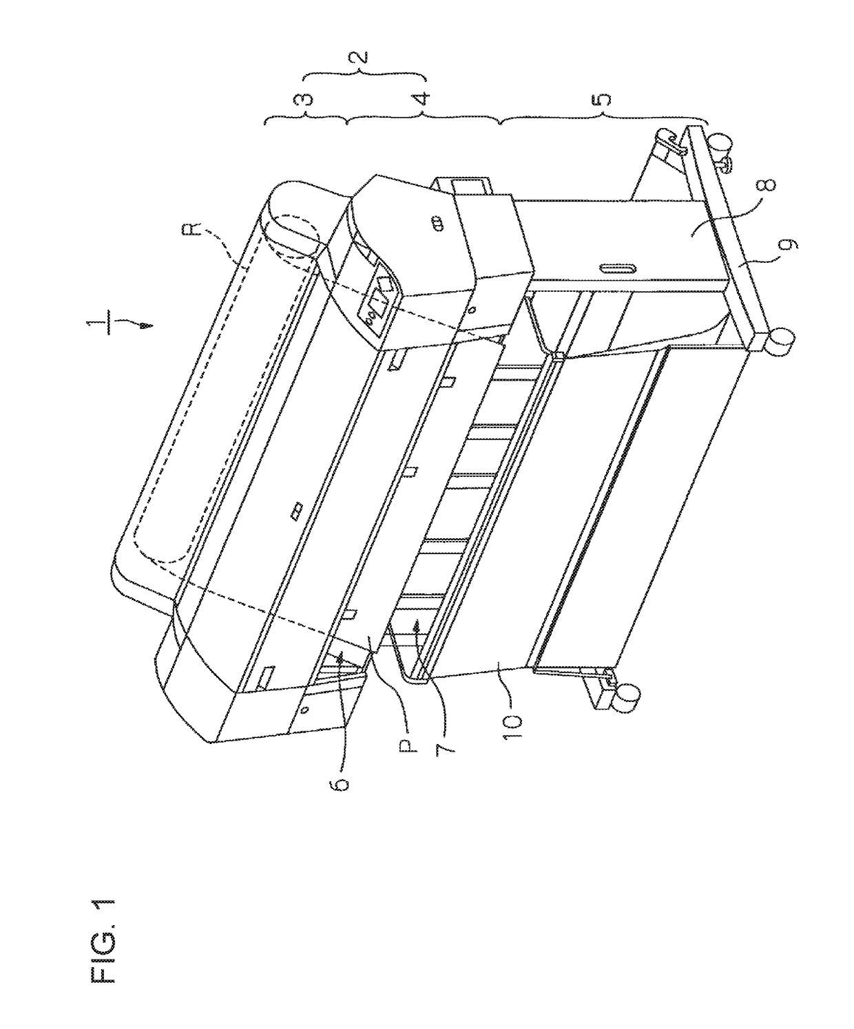
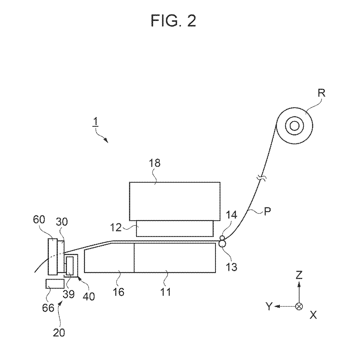
[0065]In the above-described embodiment, the cutting portion 20 is arranged on one surface side of the housing unit (downstream side of the cutting portion 20 in the transport direction); however, the structure is not limited to this. The contact portion 60 may be provided on the other surface side of the housing unit 32 (upstream side of the cutting portion 20 in the transport direction) or may be provided on both surface sides of the housing unit 32. That is, it is preferable to arrange the contact portion 60 taking into consideration the position at which the contaminants such as paper powder or the like attach to the housing unit 32. By doing this, it is possible to efficiently remove contaminants such as paper powder or the like attached to the housing unit 32.

modification example 2

[0066]The form of the contact portion 60 of the above-described embodiment is that of an anti-static brush; however, the structure is not limited to this. For example, the form of the contact portion 60 may be, other than an anti-static brush, a resin member such as a sponge or the like, or a fabric member or the like. In this way, it is possible to realize the same effect as above. Further, in the case where a resin member, cloth member, or the like serving as the contact portion 60 is used, it is preferable to divide the member into a plurality of members and arrange the members in a line in a direction (Z-axis direction) that intersects the movement direction (X-axis direction) of the cutter unit 30. Consequently, it is possible for the resin member, cloth member, or the like to contact the housing unit 32 so as to follow the shape of the surface of the housing unit 32 and it is possible to remove contaminants such as paper powder attached to the housing unit 32.

modification example 3

[0067]The lengths of the fibers 61 of the contact portion 60 of the above-described embodiment are set so as to be uniform; however, the structure is not limited to this. The length of the fibers 61 may be suitably changed in accordance with the shape of the surface of the housing unit 32 or the like. Moreover, the fibers 61 may be arranged so as to have different elasticity in accordance with the shape of the housing unit 32. By doing this, furthermore, it is possible to efficiently remove contaminants such as paper powder or the like attached to the housing unit 32. Moreover, it is possible to decrease the contact load on the housing unit 32 by the contact portion 60.


PUM


Abstract

A printing apparatus includes a printing portion that performs printing on a medium, a cutting portion that is capable of moving in a movement direction and that has cutting blades that cut the medium and a housing unit that holds the cutting blades, and a contact portion provided at a position at which the contact portion comes into contact with the housing unit when the cutting portion moves in the movement direction.

Description

BACKGROUND[0001]1. Technical Field[0002]The present invention relates to a printing apparatus and a method for removing contaminants in the printing apparatus.[0003]2. Related Art[0004]Conventionally, an image forming device provided with a transcript material cutting apparatus including a movable rotating blade and a cleaning member for wiping off ink attached to the movable rotating blade is known (for example, JP-A-2010-179467).[0005]For example, when cutting paper with the above-mentioned transcript material cutting apparatus, contaminants such as paper powder or the like formed during cutting of the paper may become attached to a housing unit that holds the movable rotating blade. However, in the above-mentioned image forming device there is a problem in that, because it does not have a function of cleaning a housing unit, contaminants which become attached to the housing unit at the time of the movement of the transcript material cutting apparatus become scattered and the scat...

Claims


Application Information

Patent Timeline
IPC IPC(8): B41J11/66B41J2/01
CPCB41J2/01B41J11/663B41F13/60B41F35/00B41J11/706B26D1/185B26D1/245B26D7/088B26D7/18B26D1/015
Inventor SATO, TAKUMI
Owner SEIKO EPSON CORP
Why Eureka
Try Eureka