Vacuum processing apparatus and method of operating the same

a vacuum processing and vacuum technology, applied in electrical devices, thin material processing, article separation, etc., can solve the problems of extension of vacuum processing chambers, insufficient consideration, and raised problems

Inactive Publication Date: 2014-02-13
HITACHI HIGH-TECH CORP
View PDF15 Cites 4 Cited by
  • Summary
  • Abstract
  • Description
  • Claims
  • Application Information

AI Technical Summary

Benefits of technology

The invention aims to prevent contamination during vacuum processing of substrates. This is achieved by using a link system that cool down the substrate to prevent high temperature processing.

Problems solved by technology

In the prior art technologies described above the following points are not sufficiently considered and a problem has been raised.
Namely, in the prior art of JP-A-9-283590, extension of the vacuum processing chambers is not considered and reinforcement of the processing capacity per unit area is not sufficiently considered.
In other words, there is a problem that extension of the processing chambers is difficult even when an attempt would be made to increase the processing capacity of the cluster-type apparatus.
Also, in the prior art of JP-A-2002-058985, not sufficiently considered is inhibiting compounds formed with products and corrosive gas adhering on a sample during the transfer of the sample from attaching to a sample and becoming contaminating objects, and there is a possibility that in the processing of a sample in the processing chamber further back viewed from the lock chamber, since unprocessed samples pass through a heat-treatment chamber which is an intermediate chamber, adhesive substances attach to the sample to generate contaminating objects.
Furthermore, even when the chamber is cooled, the contaminating objects are likely to adhere to the surface of the chamber and a problem rises that the products adhering to the surface of the chamber peel off and attach to the sample as contaminating objects to generate contamination of the sample when a sample passes through this chamber as an intermediate chamber.

Method used


Image

  • Vacuum processing apparatus and method of operating the same
  • Vacuum processing apparatus and method of operating the same
  • Vacuum processing apparatus and method of operating the same

Examples


Embodiment Construction

[0020]An embodiment of the present invention is explained with reference to the drawings.

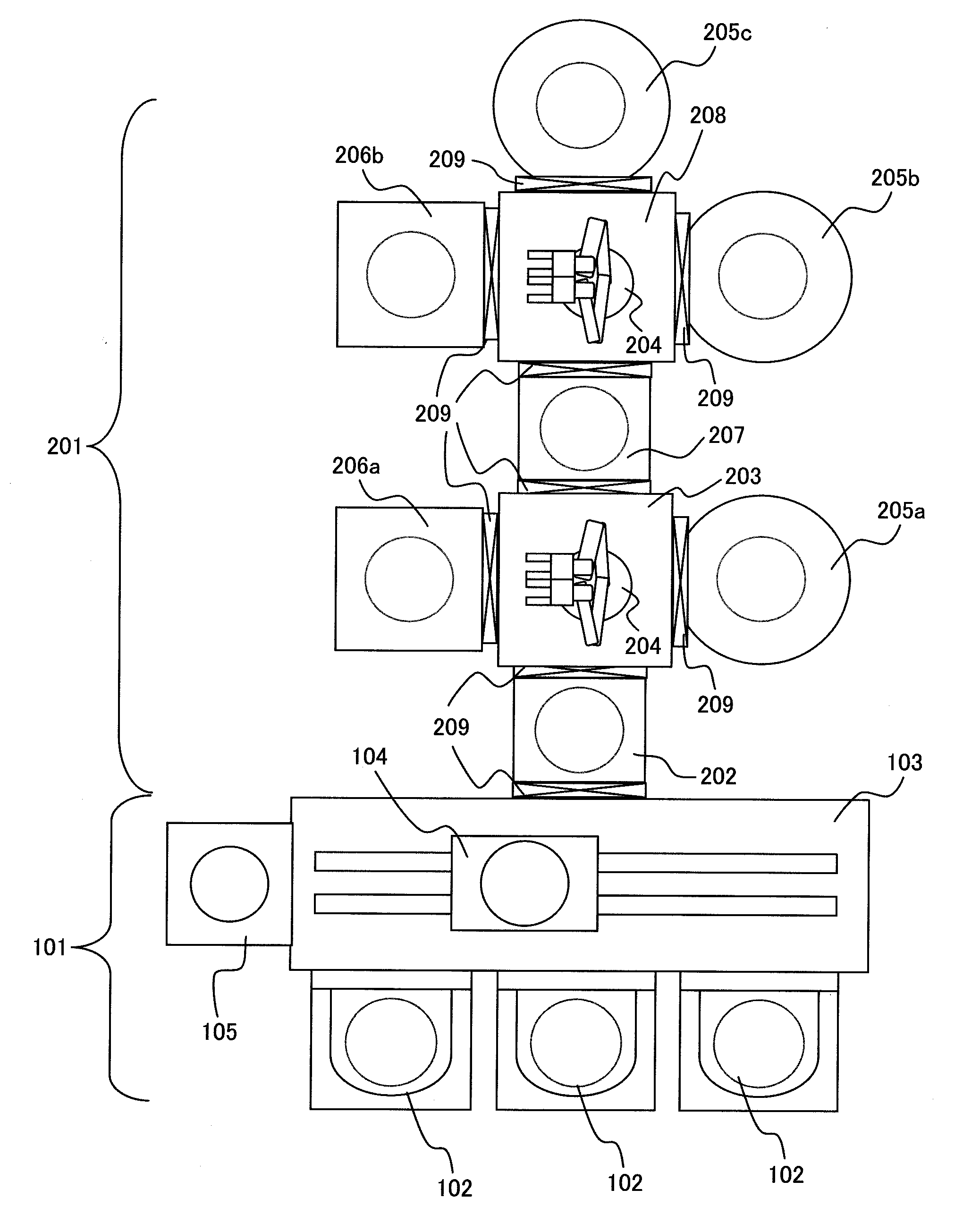
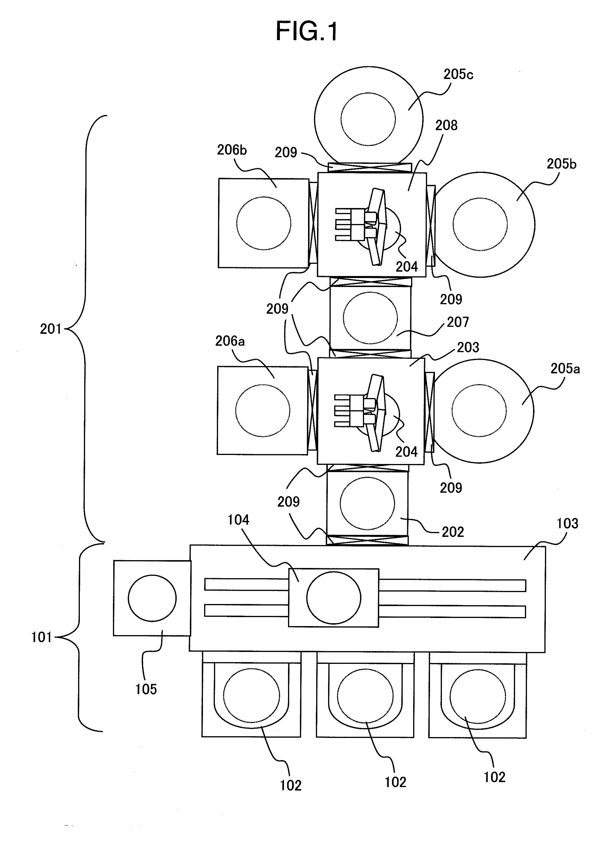
[0021]An outline of a configuration of a vacuum processing apparatus according to the present invention is explained with reference to FIG. 1. Incidentally, in the present embodiment, it is explained by way of example of installation of a plurality of ashing units and cooling units.

[0022]The vacuum processing apparatus of the present invention can be broadly divided into an atmosphere side block 101 and a vacuum side block 201. The atmosphere side block 101 is the portion where a wafer is transferred, stored, positioned, and the like at an atmospheric pressure and the vacuum side block 201 is the block where a substrate-like sample such as a semiconductor wafer is transferred at a pressure reduced from the atmospheric pressure and ashing processing and cooling processing are carried out.

[0023]The vacuum side block 201 further includes a mechanism for making pressure up and down between the atmos...


PUM


Abstract

In a vacuum processing apparatus including a plurality of vacuum transfer vessels arranged back and forth at the back of a lock chamber, an intermediate chamber arranged between them and capable of accommodating wafers, and processing units connected to respective vacuum transfer vessels, a wafer processed in a pre-processing vessel out of the processing units connected to the respective vacuum transfer vessels is transferred to a post-processing vessel connected to the same vacuum transfer vessel and post-processing is performed.

Description

BACKGROUND OF THE INVENTION[0001]The present invention relates to a vacuum processing apparatus provided with a vacuum vessel inside of which a substrate-like sample such as a semiconductor wafer transferred into a processing chamber is processed in the processing chamber and, particularly, to a vacuum processing apparatus capable of suppressing attachment of contaminating objects to the sample and an operating method of the vacuum processing apparatus.[0002]A vacuum processing apparatus having a plurality of vacuum processing vessels, in which samples such as semiconductor wafers are processed inside processing chambers arranged in the vessels, and transferring and processing one by one of a plurality of the samples sequentially in the processing vessels has been employed in the past in manufacturing of semiconductor devices. One of the most important factors in the performances in such a vacuum processing apparatus has always been to improve processing efficiency and to shorten th...

Claims


Application Information

Patent Timeline
Patent Type & Authority Applications(United States)
IPC IPC(8): H01L21/677
CPCH01L21/67745
Inventor UEMURA, TAKASHIKONDO, HIDEAKIISOZAKI, MASAKAZUSHIMOMURA, TAKAHIRO
Owner HITACHI HIGH-TECH CORP
Why Eureka
Try Eureka