Image forming apparatus

Inactive Publication Date: 2012-08-16
CANON KK
View PDF8 Cites 0 Cited by
  • Summary
  • Abstract
  • Description
  • Claims
  • Application Information

AI Technical Summary

Benefits of technology

[0014]The present invention provides an image forming apparatus, which can suppress carrier attachment caused when the density of one development device is corrected so as to be equal to those of the other development devices or can suppress the variation of a color tone of an image having high-order colors caused when the variation ratios of the densities of colors are different from each other.

Problems solved by technology

As a result, there may be degradation such as a decrease in the fluidity of the developer, and thus it is difficult to obtain an image having a desired image quality.
When an image is output, the density is deteriorated and granularity of the low density portion is worsened, so that the image quality is degraded.
However, if the contrast potential of only the development device which has been changed in the density is lowered to depart from a predetermined range, the development y (the development performance with respect to the development potential) of the development device becomes too strong.
However, in a case where the contrast potential is greatly increased, an adverse effect such as carrier attachment occurs on an image.
In this manner, in a case where the density variation occurs in one development device, if a process is performed to correct the density of the development device in which the density variation occurs, the density correction process may lead to a problem.

Method used


Image

  • Image forming apparatus
  • Image forming apparatus
  • Image forming apparatus

Examples


first embodiment

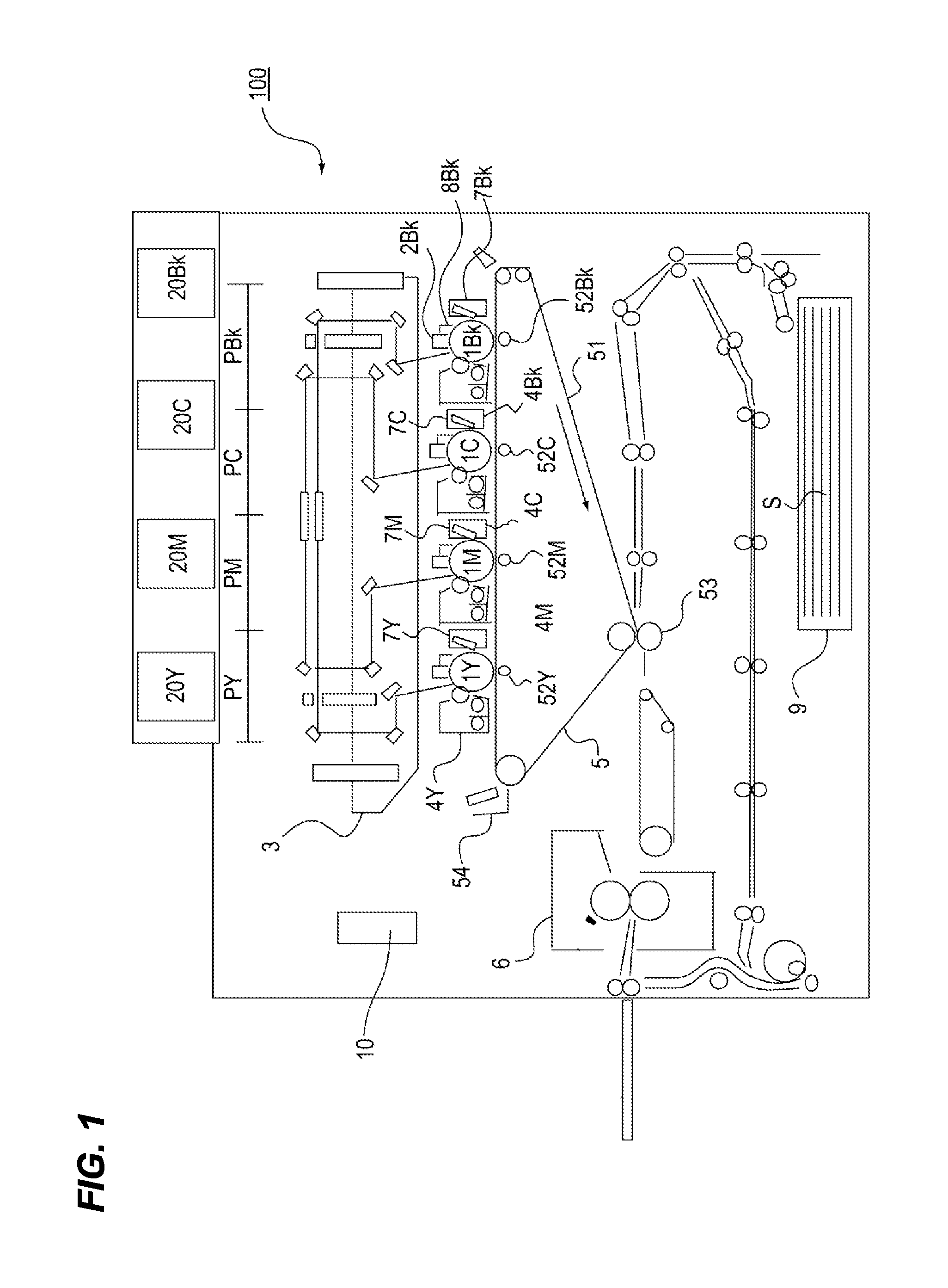
[0023]An image forming apparatus according to a first embodiment of the invention will be described with reference to the drawings. FIG. 1 is a diagram illustrating an image forming apparatus 100 according to this embodiment. As illustrated in FIG. 1, the image forming apparatus 100 includes first to fourth image forming portions PY, PM, PC, and PBK, which form color images of yellow, magenta, cyan, and black, respectively. The configurations of the respective image forming portions PY to PBK are substantially equal to each other excepting development colors. Therefore, in a case where there is not necessary to distinguish the portions from each other in the following, the description will be made as a whole without assigning the suffixes Y, M, C, and K to symbols for indicating which element belongs to a given image forming portion.

[0024]The image forming portion P includes a photosensitive drum (image bearing member) 1, a charger (charging portion) 2, an exposure device (exposure ...

second embodiment

[0048]Next, an image forming apparatus according to a second embodiment of the invention will be described with reference to the drawings. As for part of the second embodiment for which the description is already given regarding the first embodiment, that part is denoted by the same reference numerals and is not be redundantly described.

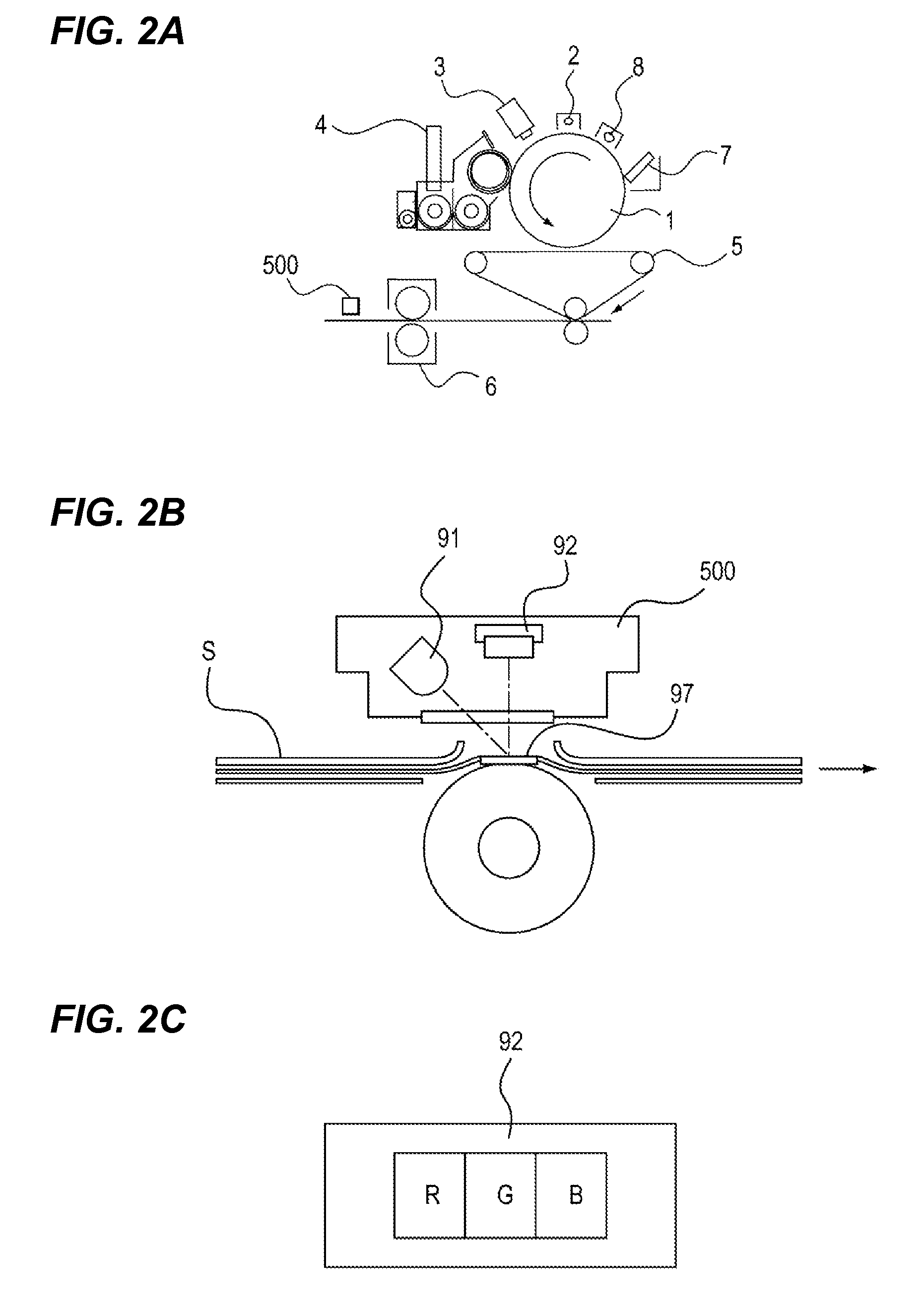
[0049]FIG. 5A is a diagram illustrating the configuration of the image forming apparatus according to this embodiment. As illustrated in FIG. 5A, the image forming apparatus according to this embodiment is provided with an optical sensor (toner quantity detecting unit) 501 instead of the density sensor 500 of the image forming apparatus 100 in the first embodiment.

[0050]As illustrated in FIG. 5B, the optical sensor 501 detects the amount of toner by reading a color patch F which is formed on the intermediate transfer belt 51 at the time of starting a print job or between the image forming operations (between sheets). The optical sensor 501 emits infr...


PUM


Abstract

A representative configuration of an image forming apparatus according to the invention is provided. The image forming apparatus has a plurality of developing devices which develops an electrostatic latent image formed on a photosensitive drum into a toner image using developer of plural colors. The image forming apparatus includes a density sensor which detects the amount of toner of the toner image for each color. In a case where it is determined that the amount of toner of any color departs from a predetermined range based on the detection result of the density sensor, a development condition of the rest developing devices other than the developing device departing from the predetermined range is changed such that the image densities developed by the respective developing devices are equal to each other.

Description

BACKGROUND OF THE INVENTION[0001]1. Field of the Invention[0002]The present invention relates to an image forming apparatus which forms an image using an electrophotographic system.[0003]2. Description of the Related Art[0004]An image forming apparatus according to the related art forms a color image using toner of four colors of yellow, magenta, cyan, and black. As a developer, a two-component developer is used which contains nonmagnetic toner particles (toner) and magnetic carrier particles (carrier). Japanese Patent Laid-Open No. 2004-177928 and Japanese Patent Laid-Open No. 9-34243 disclose a color image forming apparatus in which the colors of an output material are stabilized by stabilizing the density of each color.[0005]An image density gradually changes as the number of printed sheets increases. However, the level of the change is influenced by the contents of the formed image as well as by the number of printed sheets of the formed image. For example, an image with a relat...

Claims


Application Information

Patent Timeline
IPC IPC(8): G03G15/00G03G15/08
CPCG03G15/065G03G2215/0129G03G15/5058
Inventor NOGUCHI, AKIHIROHIROBE, FUMITAKETANAKA, SHIGERU
Owner CANON KK
Why Eureka
Try Eureka