Diverged-beam communications system

a communication system and beam technology, applied in diversity/multi-antenna systems, line-of-sight transmission, spatial transmit diversity, etc., can solve the problems of insufficient bandwidth, inability to deploy to every house and building, and inability to meet the needs of the entire house, so as to increase the angular tolerance between transmitters, reduce costs, and increase the output power of lasers and detector arrays. the effect of sensitivity

Inactive Publication Date: 2018-02-15
8 RIVERS CAPTTAL LLC
View PDF39 Cites 51 Cited by
  • Summary
  • Abstract
  • Description
  • Claims
  • Application Information

AI Technical Summary

Benefits of technology

The FSO system described in this patent offers a solution for the need for affordable, high-bit rate communication in the last mile and mobile markets. The system uses diverged laser beams to create and detect photons over a range of angles, resulting in increased angular tolerance between transmitters and receivers. This allows for non-line-of-sight communication and the use of multiple beam paths to reduce the impact of weather. The system also utilizes optical frequencies to provide a large amount of bandwidth for use. Overall, the system offers a more cost-effective and efficient solution for high-bit rate communication.

Problems solved by technology

But available bandwidth is starting to run short in all cases except FTTH, which remains too expensive for deployment to every house and building.

Method used


Image

  • Diverged-beam communications system
  • Diverged-beam communications system
  • Diverged-beam communications system

Examples


Embodiment Construction

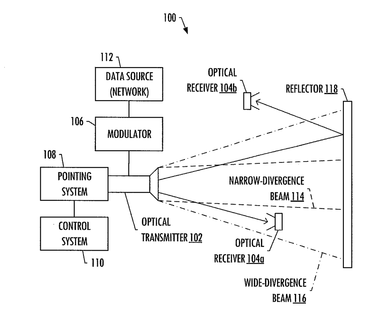
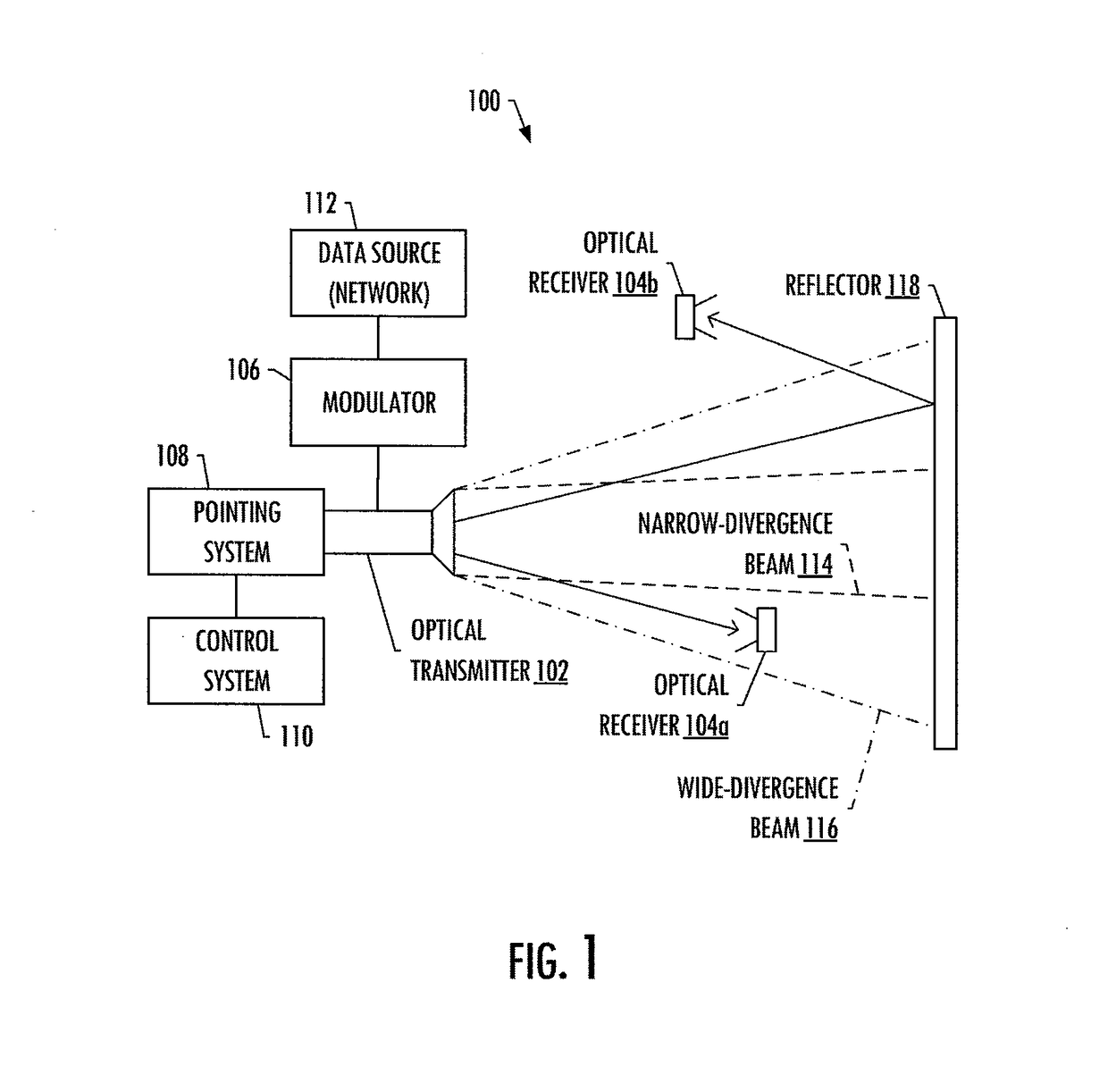
[0057]The present disclosure will now be described more fully hereinafter with reference to example implementations thereof. These example implementations are described so that this disclosure will be thorough and complete, and will fully convey the scope of the disclosure to those skilled in the art. Indeed, the disclosure may be embodied in many different forms and should not be construed as limited to the implementations set forth herein; rather, these implementations are provided so that this disclosure will satisfy applicable legal requirements. As used in the specification and the appended claims, for example, the singular forms “a,”“an,”“the” and the like include plural referents unless the context clearly dictates otherwise. Also, for example, reference may be made herein to quantitative measures, values, relationships or the like. Unless otherwise stated, any one or more if not all of these may be absolute or approximate to account for acceptable variations that may occur, ...


PUM


Abstract

An apparatus is provided that includes a modulator and an optical transmitter coupled to the modulator and configured to emit an optical beam that the modulator is configured to modulate with data. The optical transmitter may thereby be configured to emit the optical beam carrying the data and without artificial confinement for receipt by an optical receiver configured to detect and recover the data from the optical beam. The optical transmitter may be configured to emit the optical beam with a divergence angle greater than 0.1 degrees, and with a photonic efficiency of less than 0.05%. The photonic efficiency may relate a number of photons of the optical beam detectable by the optical receiver, to a number of photons of the optical beam emitted by the optical transmitter.

Description

CROSS-REFERENCE TO RELATED APPLICATION(S)[0001]The present application is a division of U.S. patent application Ser. No. 14 / 593,149, entitled: Diverged-Beam Communications System, filed on Jan. 9, 2015, which claims priority to U.S. Provisional Patent Application No. 61 / 925,889, entitled: Beam Communications System, filed on Jan. 10, 2014, the contents of both of which are incorporated herein by reference in their respective entireties.TECHNOLOGICAL FIELD[0002]The present disclosure relates generally to optical communications and in particular, diverged-beam optical communications.BACKGROUND[0003]The concept of free space optical (FSO) communications using lasers dates back to the invention of the laser. However, difficulties with generating and modulating high-power lasers have restricted the use of FSO to line-of-sight systems using tightly-collimated beams. Very low-power and low-modulation-rate with diverged pulses of light has been used in a few niche applications such as remot...

Claims


Application Information

Patent Timeline
Patent Type & Authority Applications(United States)
IPC IPC(8): H04B10/112H04B7/06H04B10/50H04B10/116
CPCH04B10/503H04B10/116H04B7/0617H04B10/1123H04B10/1141H04B10/1149
Inventor PALMER, MILES R.OSADZINSKI, ALEKSANDER EDWARDBROWN, WILLIAM J.
Owner 8 RIVERS CAPTTAL LLC
Why Eureka
Try Eureka