
Spiral clean pulley

Active Publication Date: 2018-03-01
DOUGLAS MFG
View PDF2 Cites 0 Cited by
  • Summary
  • Abstract
  • Description
  • Claims
  • Application Information

AI Technical Summary

Benefits of technology

The invention aims to improve the cleaning of roller pulleys while still providing superior belt support. Additionally, it seeks to make the manufacture of roller pulleys more modular, allowing for the creation of pulleys of various sizes.

Problems solved by technology

Roller pulleys in conveyor systems suffer from the inherent accumulation of tramp material on the belt as the material passes between the belt and the pulley.
Numerous designs have been proposed to open the solid surface of the roller pulley with a number of supporting structures, however each of these attempts has had limitations in terms of belt support, tramp migration, and effectiveness.
Known roller pulleys which attempt to open the solid surface are generally customized for use on a specific size conveyor, thus in the manufacturing process efficiencies of manufacture are not obtained because each size roller pulley has its own manufacturing setup cost.

Method used


Image

  • Spiral clean pulley
  • Spiral clean pulley
  • Spiral clean pulley

Examples


Embodiment Construction

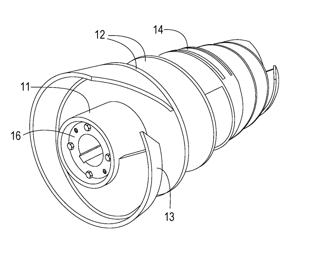
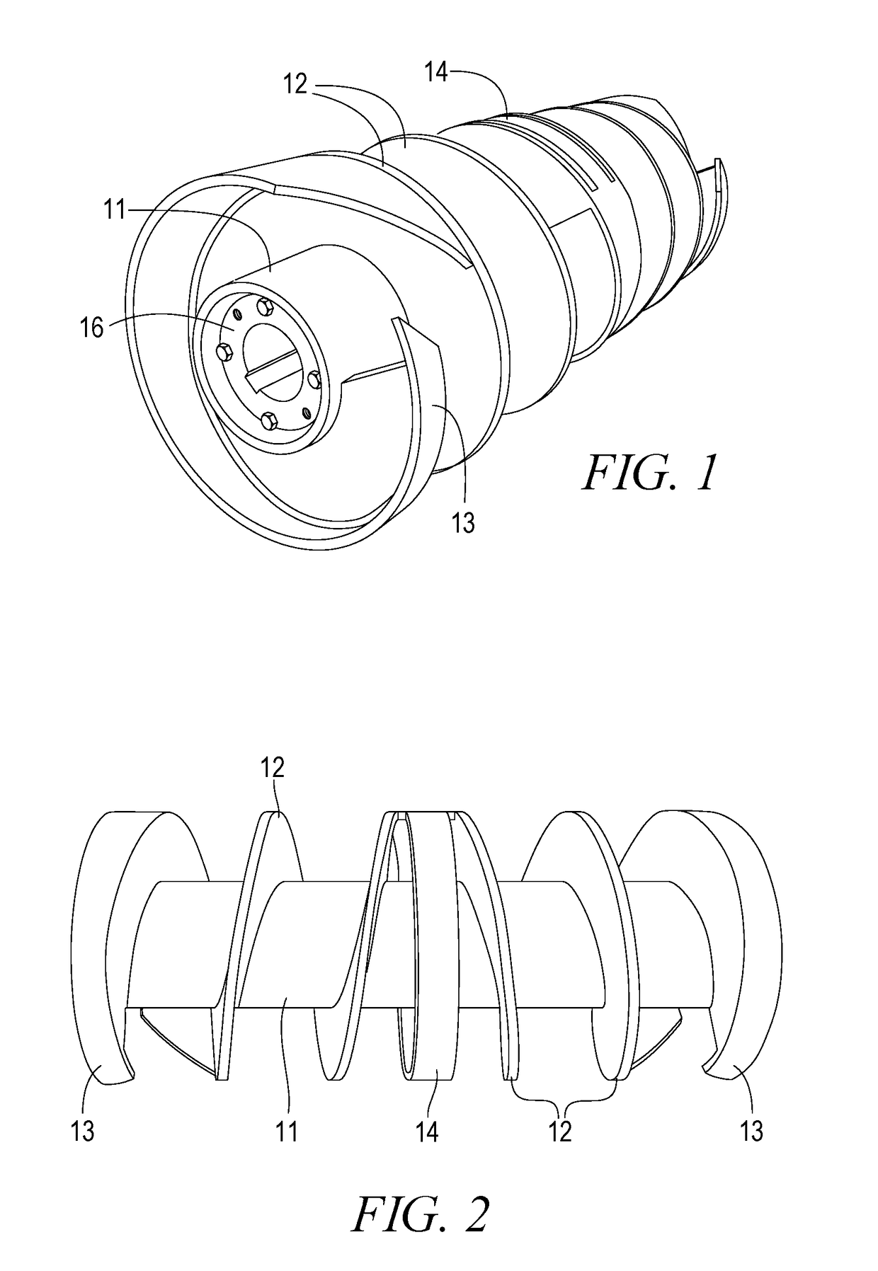
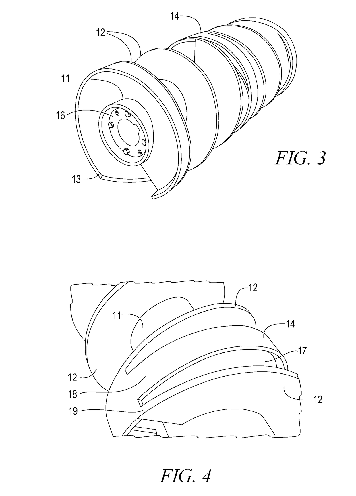
[0016]Referring to the drawings for a clearer understanding of the invention, it will be seen that our pulley utilizes a standard core 11 having a set diameter. This generally tubular member meets CEMA / ANSI specifications is the main building block of our pulleys. Core 11 is to be utilized throughout the various sizes of pulleys to be kept in inventory, thus the core 11 may be used in our products ranging from 12 to 24 inches in diameter and 26 to 63 inch in face width. The figures show that the end face 16 of the core if fitted with hubs and bushings to allow the pulley to be mounted to the conveyor frame as is well known and understood.

[0017]Mounted on core 11 at or near the center thereof is our reinforced center section 14 which provides support over a wide area in the center of the roller pulley. Reinforced center section 14 includes an inner disc 17 and wide annulus 18 that provides support and stability to the belt. The disclosure is not intended to be limiting but in the int...


PUM


Abstract

A conveyor pulley design incorporates a plow design that forces tramp material away from the belt and discharges material down and away from the belt, bearings, take-up assembly, maintenance equipment and personnel. The pulley uses a modular construction that allows for optimized manufacture and inventory processes and reduces the materials cost in the pulley

Description

FIELD OF INVENTION[0001]The present invention relates to a pulley for a conveyer system and in even greater particularity to a self-cleaning pulley that provides excellent support to the belt of the system. In greater particularity, our innovation allows for modular construction of cores, end plows, and center sections of a pulley. The core can be uniformly sized for use on multiple pulley diameter sizes. In a similar manner, the end plows and center section can be used on all pulley face widths of the same diameter. In addition to modularity, our invention relates to the load bearing and self-cleaning design of such pulleys.BACKGROUND[0002]Roller pulleys in conveyor systems suffer from the inherent accumulation of tramp material on the belt as the material passes between the belt and the pulley. Numerous designs have been proposed to open the solid surface of the roller pulley with a number of supporting structures, however each of these attempts has had limitations in terms of bel...

Claims


Application Information

Patent Timeline
IPC IPC(8): B65G39/073F16H55/36B65G45/20
CPCB65G39/073F16H55/36F16H57/04B65G45/00B65G45/20F16H55/566
Inventor ROSS, PAULBREWER, BENJAMINCHAMORRO, ALBERTOGRIZZELL, DENNISCARLISLE, JEFFERY
Owner DOUGLAS MFG
Learn More