
Moisture path close-out and thermal control system and methods of assembling same

Active Publication Date: 2018-03-08
THE BOEING CO
View PDF5 Cites 4 Cited by
  • Summary
  • Abstract
  • Description
  • Claims
  • Application Information

AI Technical Summary

Benefits of technology

[0004]There is provided, a moisture control assembly for use with a support extending through an insulation layer, the insulation layer positioned between an outer wall and the inner wall, the assembly comprising: a moisture path close-out structure coupled to the insulation layer at an aperture defined through the insulation layer, the moisture path close-out structure including an opening substantially aligned with the apertu

Problems solved by technology

However, at some locations, structures and/or supports can protrude through the insulation blanket.
However, th

Method used


Image

  • Moisture path close-out and thermal control system and methods of assembling same
  • Moisture path close-out and thermal control system and methods of assembling same
  • Moisture path close-out and thermal control system and methods of assembling same

Examples


Example

Generally

[0036]The present disclosure generally relates to the moisture control field. More particularly, the present disclosure relates to the field of moisture control in a vehicle.

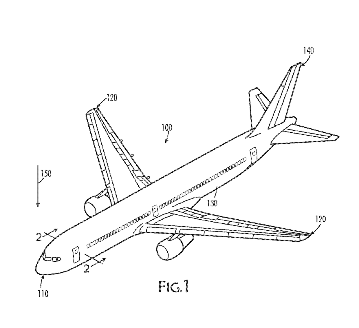
[0037]FIGS. 1-2 illustrate moisture flow in an exemplary aircraft, while FIGS. 3-6 show an exemplary moisture path close-out and thermal control system for preventing or at least minimizing moisture flow into an inner cabin portion of the aircraft, according to some aspects of the disclosure. FIG. 1 shows an aircraft 100 that includes a nose 110, wings 120, a fuselage 130, and a tail 140. FIG. 1 also illustrates a downward arrow 150 indicating the expected direction in which the force of gravity will pull objects, such as liquid water, onboard an aircraft 100 in a nominal operational profile.

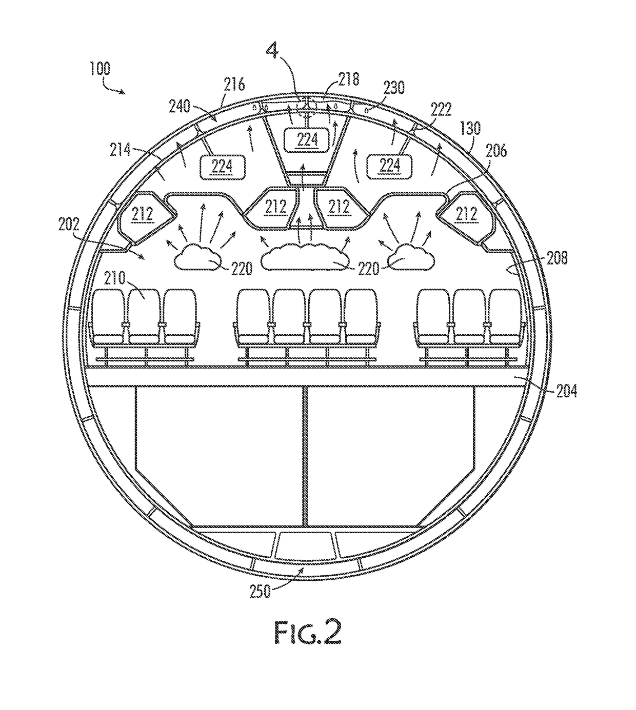
[0038]FIG. 2 is a cross-sectional, schematic view of the aircraft 100 indicated by view arrows 2 in FIG. 1. FIG. 2 illustrates a portion of the aircraft fuselage 130, simplified for easier understanding of this Desc...


PUM


Abstract

A moisture control assembly for use with a support beam extending through an insulation layer is provided. The insulation layer is positioned between an outer wall and an inner wall. The assembly includes: a moisture path close-out structure coupled to the insulation layer at an aperture defined through the insulation layer, the moisture path close-out structure including an opening substantially aligned with the aperture and configured to receive the support beam therethrough; and a coupling mechanism configured to secure the moisture path close-out structure to the support beam such that the moisture path close-out structure is partially pulled away from the insulation layer, the coupling mechanism and the moisture path close-out structure configured to direct liquid flow down and away from the support beam and along the insulation layer.

Description

FIELD[0001]The present disclosure generally relates to the moisture control field. More particularly, the present disclosure relates to the field of moisture control in a vehicle.BACKGROUND[0002]In an aircraft, the outer skin is spaced from the walls and ceiling of a passenger cabin (or other compartment), and the gap is at least partially filled with an insulation layer or blanket. The insulation layer is typically formed from a waterproof material. During a flight, liquid from moist air can condense against the skin and freeze during cruise. During decent, this frozen liquid can thaw and drip back down towards the cabin. Because the insulation blanket is waterproof, the condensate can flow along the insulation blanket and drain into the bilge. However, at some locations, structures and / or supports can protrude through the insulation blanket. For example, the supports that hold monuments and bins to the crown extend from the structure at the skin, through the insulation blanket, an...

Claims


Application Information

Patent Timeline
IPC IPC(8): B64C1/06B64F5/00
CPCB64F5/0009B64C1/067B64C1/40F16L59/12B64F5/10B64F5/20B64F5/40
Inventor BERRYESSA, BRIAN PATRICK
Owner THE BOEING CO
Features
  • Generate Ideas
  • Intellectual Property
  • Life Sciences
  • Materials
  • Tech Scout
  • Unparalleled Data Quality
  • Higher Quality Content
  • 60% Fewer Hallucinations
Learn More