Tracking and guidance arrangement for a surgical robot system and related method

Active Publication Date: 2018-03-22
NEOCIS
View PDF15 Cites 8 Cited by
  • Summary
  • Abstract
  • Description
  • Claims
  • Application Information

AI Technical Summary

Benefits of technology

This patent describes a tracking and guidance system for a surgical robot system. The system includes a patient-interacting device with an instrument attached to a guide arm. The instrument is designed to interact with the maxillofacial anatomy of a patient. The system also includes a fiducial marker coupled to the patient's anatomy and a detector positioned adjacent to the marker. The detector interacts with the marker, and a controller device receives data from the detector and determines the spatial relation between the marker and the detector. This relationship is used to direct the instrument to interact with the patient's anatomy. This system provides precise guidance for the surgical robot system and improves the accuracy and safety of the surgical procedure.

Problems solved by technology

However, a mechanical tracking arm that is physically attached or otherwise tethered to a patient may disadvantageously create a weight on the patient and physically constrain patient motion.
This may lead to patient discomfort during the procedure.
For example, a remote optical tracking system using a stereoscopic camera requires line-of-sight to one or more fiducial markers in a large field of view, which may lead to constant repositioning of the surgical instruments, equipment, and the like, or else the line of communication (i.e., sight in the case of an optical tracking system) may otherwise be impeded during the procedure.
In another example, an electromagnetic tracking system may equally be disadvantageous as interference or interruption of communication may occur, which may inhibit or prevent system efficiency.

Method used


Image

  • Tracking and guidance arrangement for a surgical robot system and related method
  • Tracking and guidance arrangement for a surgical robot system and related method
  • Tracking and guidance arrangement for a surgical robot system and related method

Examples


Embodiment Construction

[0013]The present disclosure now will be described more fully hereinafter with reference to the accompanying drawings, in which some, but not all aspects of the disclosure are shown. Indeed, the disclosure may be embodied in many different forms and should not be construed as limited to the aspects set forth herein; rather, these aspects are provided so that this disclosure will satisfy applicable legal requirements. Like numbers refer to like elements throughout.

[0014]Various aspects of the present disclosure may be at least partially based on a guided surgical robotic system and method such as that disclosed, for example, in U.S. Pat. No. 8,808,000 to Salcedo et al. and assigned to Neocis, also the assignee of the present application. The disclosure of U.S. Pat. No. 8,808,000 to Salcedo et al. is thus incorporated by reference herein.

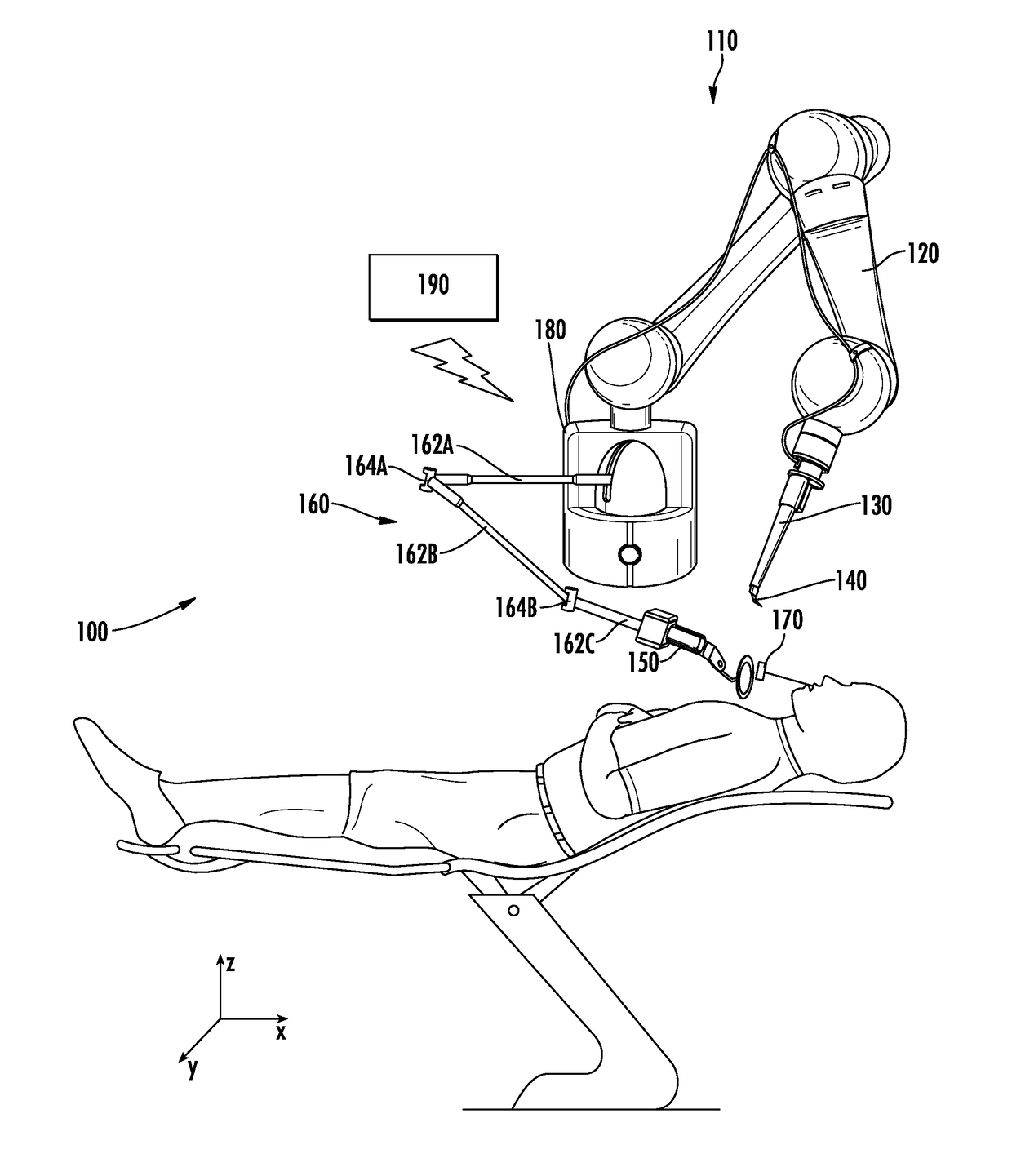
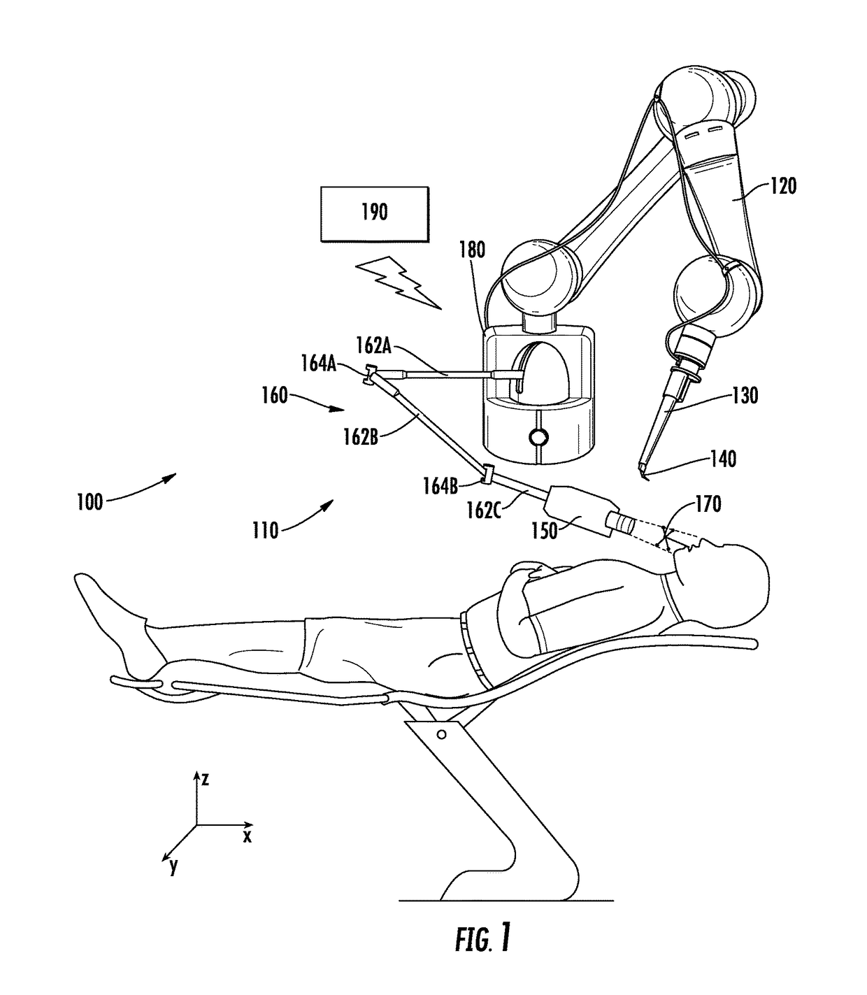
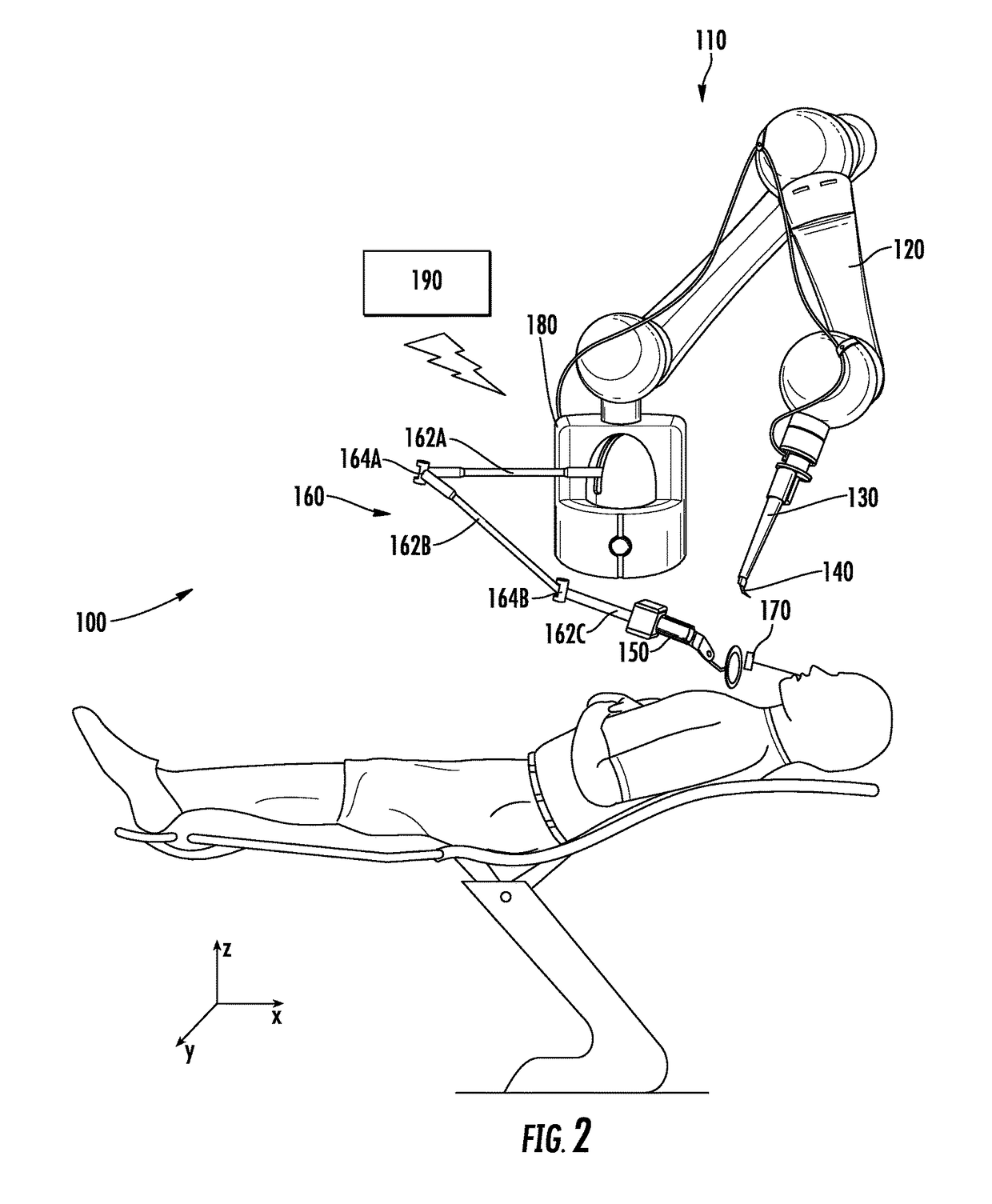
[0015]FIGS. 1-3 provide exemplary embodiments of tracking and guidance arrangements for surgical robot systems and associated methods. According to s...


PUM


Abstract

A tracking and guidance arrangement for a surgical robot system and related method are provided. The arrangement includes a patient-interacting device including an instrument engaged a distal end of a guide arm and a fiducial marker coupled to maxillofacial anatomy of the patient. A detector is connected to an articulating arm and co-operable therewith to be positioned adjacent to the fiducial marker, with the detector being configured to interact with the fiducial marker. A controller device is configured to receive data from the detector relative to the interaction thereof with the fiducial marker, to determine a spatial relation between the fiducial marker and the detector based on the data, to determine a spatial relation of the instrument relative to the fiducial marker, and to direct the instrument to interact with the maxillofacial anatomy of the patient according to the determined spatial relations.

Description

BACKGROUNDField of the Disclosure[0001]The present application relates to surgical robots and associated guidance systems and, more particularly, to a tracking and guidance arrangement for a surgical robot system used, for example, in dental surgery, wherein the arrangement is configured to track patient movement during the surgical procedure in order to guide a surgical instrument.Description of Related Art[0002]Many surgical robot systems for procedures such as dental surgery procedures utilize guidance systems comprising a robotic arm to guide a surgical instrument (e.g., a drill) and a mechanical tracking arm coupled to a patient to track patient motion relative to the surgical instrument. In these systems, the robotic arm and the mechanical tracking arm are physically coupled together and calibrated so their relative positions are known. To track patient movement, the mechanical tracking arm may be either physically attached or otherwise tethered to the patient via a splint or ...

Claims


Application Information

Patent Timeline
IPC IPC(8): A61C1/00A61B34/20A61B34/30A61C1/14A61C3/02
CPCA61C1/0015A61B34/20A61B34/30A61B2034/2063A61C3/02A61B2034/2051A61B2034/2055A61C1/145A61B90/50A61B2034/2059A61C1/084A61B2034/2057A61B2034/2072A61B2090/397A61B2090/3937A61C1/00A61B90/39A61C8/0089A61B2034/2074A61B2034/2068A61B2090/3983
Inventor MOZES, ALONVAISH, SARVAGYACOLE, DAVID PETERANDERSON, RYANHE, WUWEISALCEDO, JUANMCMAHAN, WILLIAM CHU-HYON
Owner NEOCIS
Why Eureka
Try Eureka