
Synthetic Turf Seam Integration Template System and Methods of Use

a template system and synthetic turf technology, applied in the field of hand tools, can solve the problems of not being satisfactory to the homeowner or business owner, the ridged seam will not improve, etc., and achieve the effect of reducing the possibility of user error and efficient us

Active Publication Date: 2018-03-29
WADKINS JOE DENNIS
View PDF1 Cites 2 Cited by
  • Summary
  • Abstract
  • Description
  • Claims
  • Application Information

AI Technical Summary

Benefits of technology

The invention provides a system for integrating the edges of two sections of synthetic turf to create an imperceptible seam. The system includes two templates: a primary template and a coordinating template. The primary template has a specific curvature pattern, and the coordinating template has a complementary curvature pattern. This allows the two templates to fit together without needing an offset. The system also includes a connector that can be used to join the two templates together, saving time and making the integration process easier for larger installations. Overall, this system simplifies the process of integrating synthetic turf and creates a seam that is difficult to notice.

Problems solved by technology

Often, however, when installing synthetic turf there is a need to use multiple pieces of turf, because the predetermined turf lateral width provided by the manufacturer is too narrow to cover the width of the turf installation area.
However, this standard method of seam formation often creates a problem.
A ridged seam will not improve over time, but will continue to have an upward thrust at the abutting edges, which will not be satisfactory to the homeowner or business owner who is having the synthetic turf installed.

Method used


Image

  • Synthetic Turf Seam Integration Template System and Methods of Use
  • Synthetic Turf Seam Integration Template System and Methods of Use
  • Synthetic Turf Seam Integration Template System and Methods of Use

Examples


Embodiment Construction

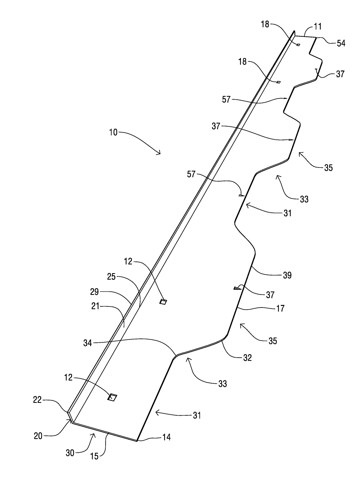
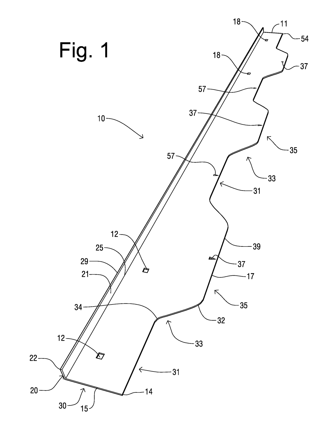
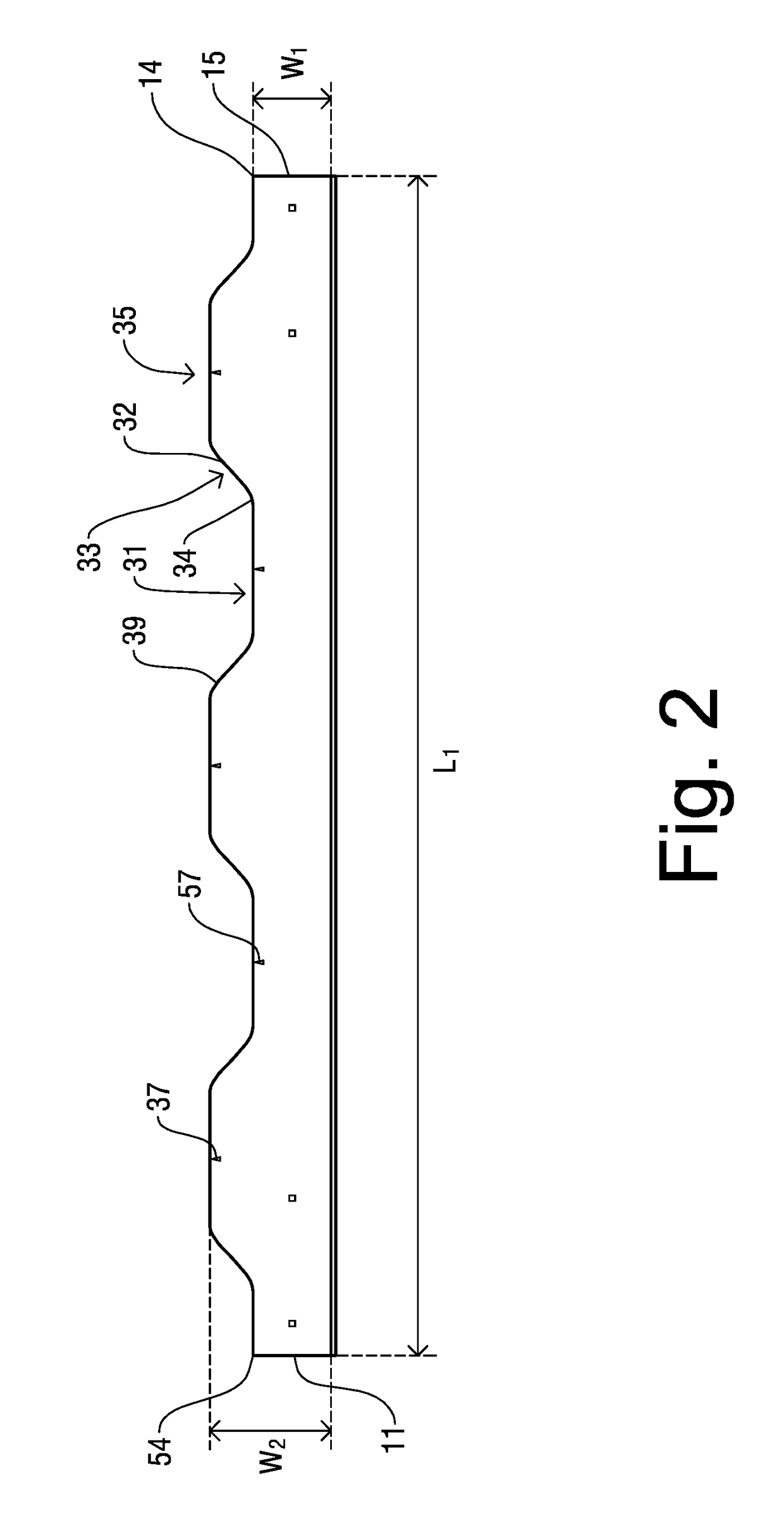
[0031]Shown throughout the figures, the present invention is directed toward a synthetic turf seam integration template, template system, and methods of utilizing a single template, two duplicate templates, a coordinating template set, and / or other parts of the template system. A first embodiment (shown in FIGS. 1-2, 5, 6, 10) discloses a single template 10 with a primary curvature pattern. This single template 10 can be used alone, can be used in combination with an optional connector 40 (FIGS. 3-4) with a duplicate template 10 having the primary curvature pattern, or can be used with a coordinating template 110 of the second embodiment that has a complementary curvature pattern. The second embodiment (shown in FIGS. 7 and 12) includes both the primary template 10 with the primary curvature pattern and a coordinating template 110, which has a curvature pattern that is the complement of the primary curvature pattern. Variations in the curvature pattern are also disclosed. Methods of...


PUM

PropertyMeasurementUnit
lengthaaaaaaaaaa
lengthaaaaaaaaaa
lengthaaaaaaaaaa

Abstract

A synthetic turf seam integration template system and method is provided that includes a template having a planar base with a perpendicularly joined positioner. The planar base is configured with a longitudinal cutting edge with a predetermined curvature and an opposing longitudinal non-cutting edge. The positioner, which aids in moving the template, is attached to the non-cutting edge. Variations of the predetermined curvature patterns are disclosed. An optional connector allows connection of two templates to create a longer template for usage on longer seams. Also disclosed are methods of using the seam integration tool in creating an undetectable seam in synthetic turf.

Description

CROSS-REFERENCE TO RELATED APPLICATIONS[0001]The present nonprovisional application is a continuation-in-part application of currently pending U.S. patent application Ser. No. 14 / 839,816 filed on Aug. 28, 2015, now U.S. Pat. No. 9,833,920, which is incorporated by reference herein in its entirety.FIELD OF INVENTION[0002]This invention relates generally to hand tools for manual use and, more particularly, to a template and template system for cutting synthetic turf with methods of using the template system to create an inconspicuous turf seam.BACKGROUND OF THE INVENTION[0003]Replacing grass with artificial or synthetic turf provides several advantages, such as greatly reducing the need for lawn maintenance and eliminating the use of water for lawn irrigation. Synthetic turf is fabricated with an upward-facing synthetic grass face formed by tufts of grass (and, optionally, additional thatch tufts) and a downward-facing backing or understructure that supports the synthetic tufts of the...

Claims


Application Information

Patent Timeline
Patent Type & Authority Applications(United States)
IPC IPC(8): B26B29/06B29C65/74B29C65/48
CPCB26B29/06B29C65/74B29C65/48B29C65/5042B29C66/02241B29C66/1142B29C66/221B29C66/229B29C66/305B29C66/43B29L2031/722B29L2031/732
Inventor WADKINS, JOE DENNIS
Owner WADKINS JOE DENNIS
Learn More