Musical sound generating device, control method for same, storage medium, and electronic musical instrument

a technology of musical sound and generating device, which is applied in the direction of instruments, electrotrophonic musical instruments, etc., can solve the problem of not knowing the technique of suitably modeling a mouthpi

Active Publication Date: 2018-03-29
CASIO COMPUTER CO LTD
View PDF8 Cites 12 Cited by
  • Summary
  • Abstract
  • Description
  • Claims
  • Application Information

AI Technical Summary

Benefits of technology

[0007]To achieve these and other advantages and in accordance with the purpose of the present invention, as embodied and broadly described, in one aspect, the present disclosure provides a musical sound generating device, including: one or more operating units having sensors that detect operations of a performer; a processor communicating with the one or more operating units, wherein the processor is configured to perform the following: determine a reflection coefficient of a progressive wave and a regressive wave using a mouthpiece model that models a mouthpiece as a three-dimensional shape having one end at which the mouthpiece is to be held in a mouth of the performer being smaller than another end, the progressive wave progressing through the modeled mouthpiece from the one end to the another end and the regressive wave regressing through the modeled mouthpiece from the another end to the one end, the reflection coefficient being determined by determined a wave impedance for the progressive wave and determining a wave impedance for the regressive wave; and generate a musical sound signal on the basis of the determined reflection coefficient and an operation of the performer sensed by the one or more operating units, and outputs the musical sound signal to a sound generator for sound production.
[0008]In another aspect, the present disclosure provides a method of generating a musical sound by a musical sound generating device having a processor and a sound generator that is connected to the processor, the method comprising causing the processor to perform the following: determine a reflection coefficient of a progressive wave and a regressive wave using a mouthpiece model that models a mouthpiece as a three-dimensional shape having one end at which the mouthpiece is held in a mouth of a performer being smaller than another end, the progressive wave progressing through the mouthpiece model from the one end to the another end and the regressive wave regressing through the mouthpiece model from the another end to the one end, the reflection coefficient being determined by determining a wave impedance for the progressive wave and a wave impedance for a second wave impedance of the regressive wave; generate a musical sound signal on the basis of the determined reflection coefficient; and output the musical sound signal to the sound generator for sound production.
[0009]In another aspect, the present disclosure provides a non-transitory storage medium having stored therein instructions executable by a processor in a musical sound generating device, the instructions causing the processor to perform the following: determine a reflection coefficient of a progressive wave and a regressive wave using a mouthpiece model that models a mouthpiece as a three-dimensional shape having one end at which the mouthpiece is held in a mouth of a performer being smaller than another end, the progressive wave progressing through the mouthpiece model from the one end to the another end and the regressive wave regressing through the mouthpiece model from the another end to the one end, the reflection coefficient being determined by determining a wave impedance for the progressive wave and a wave impedance for a second wave impedance of the regressive wave; generate a musical sound signal on the basis of the determined reflection coefficient; and output the musical sound signal to a sound generator in the musical sound generating device for sound production.

Problems solved by technology

Conventionally, however, there is no known technique for suitably modelling a mouthpiece.

Method used


Image

  • Musical sound generating device, control method for same, storage medium, and electronic musical instrument
  • Musical sound generating device, control method for same, storage medium, and electronic musical instrument
  • Musical sound generating device, control method for same, storage medium, and electronic musical instrument

Examples


Embodiment Construction

[0019]Hereafter, one embodiment for realizing the present invention will be described in detail while referring to the drawings.

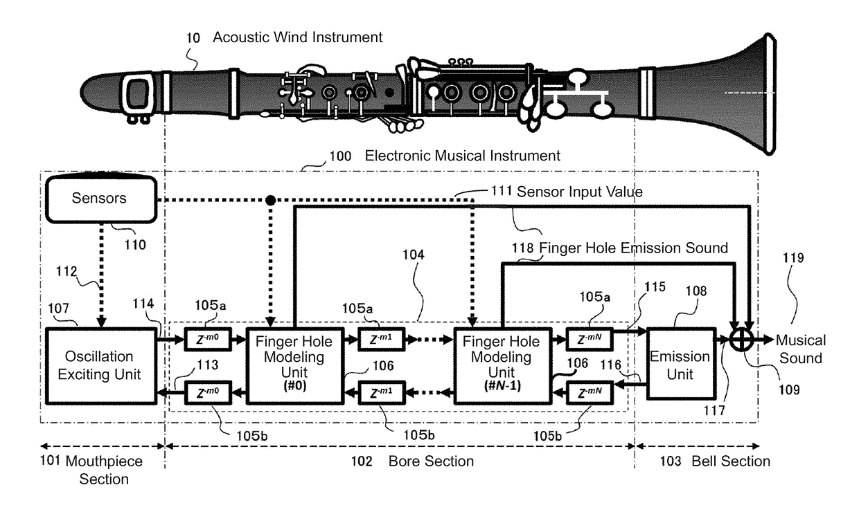
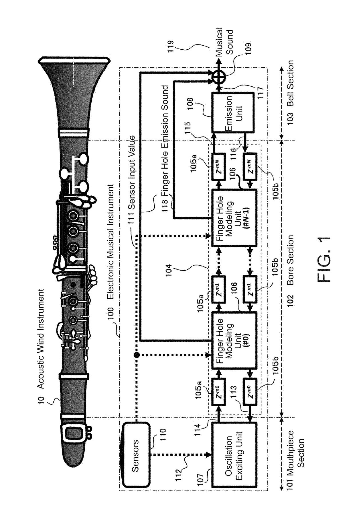
[0020]FIG. 1 illustrates a block diagram of an electronic musical instrument 100 according to one embodiment of the present invention. The electronic musical instrument 100 contains a physical model sound source that physically models the acoustic characteristics of an acoustic wind instrument 10, which is, for example, a clarinet that is illustrated above the block diagram for the sake of comparison. The electronic musical instrument has a mouthpiece section 101, a bore section 102, and a bell section 103 corresponding to the respective parts of the acoustic wind instrument 10.

[0021]First, the bore section 102, which plays a central role in the physical modelling of the electronic musical instrument 100, includes a delay line section 104. The delay line section 104 executes delay line processing in which propagation of a progressive wave and a regressive w...


PUM


Abstract

An electronic musical instrument uses a mouthpiece model that models a mouthpiece as a three-dimensional shape having one end at which the mouthpiece is to be held in a mouth of a performer being smaller than another end. A processor in the instrument calculates a reflection coefficient of a progressive wave and a regressive wave using the mouthpiece model by calculating a wave impedance for the progressive wave and calculating a wave impedance for the regressive wave, and generates a musical sound signal on the basis of the calculated reflection coefficient, which is then outputted to a sound generator for sound production.

Description

BACKGROUND OF THE INVENTIONTechnical Field[0001]The present invention relates to a musical sound generating device, a control method for the musical sound generating device, a storage unit, and an electronic musical instrument.Background Art[0002]Conventionally, devices have been proposed that synthesize musical sound by modeling the sound-producing principles of musical instruments (hereafter, referred to as “modeling sound sources”) (the related art disclosed in Patent Document 1, for example). In this conventional technology, the disclosed musical sound synthesizing device synthesizes the musical sound of a wind instrument. An input device specifies any of a plurality of fingerings corresponding to the same pitch in accordance with an operation performed by a user. A variable control unit sets variables such that the variables change in accordance with the fingering specified by the input device. A musical sound synthesizing unit synthesizes a musical sound in accordance with the...

Claims


Application Information

Patent Timeline
Patent Type & Authority Applications(United States)
IPC IPC(8): G10H5/00G10H1/06G10H1/043
CPCG10H5/007G10H1/06G10H2250/465G10H2230/241G10H2220/361G10H1/043G10H7/02G10H2230/205G10H2250/141G10H2250/515G10H2250/521
Inventor KASUGA, KAZUTAKA
Owner CASIO COMPUTER CO LTD
Why Eureka
Try Eureka