Electric wire holder and wire harness
- Summary
- Abstract
- Description
- Claims
- Application Information
AI Technical Summary
Benefits of technology
Problems solved by technology
Method used
Image

Examples
first embodiment
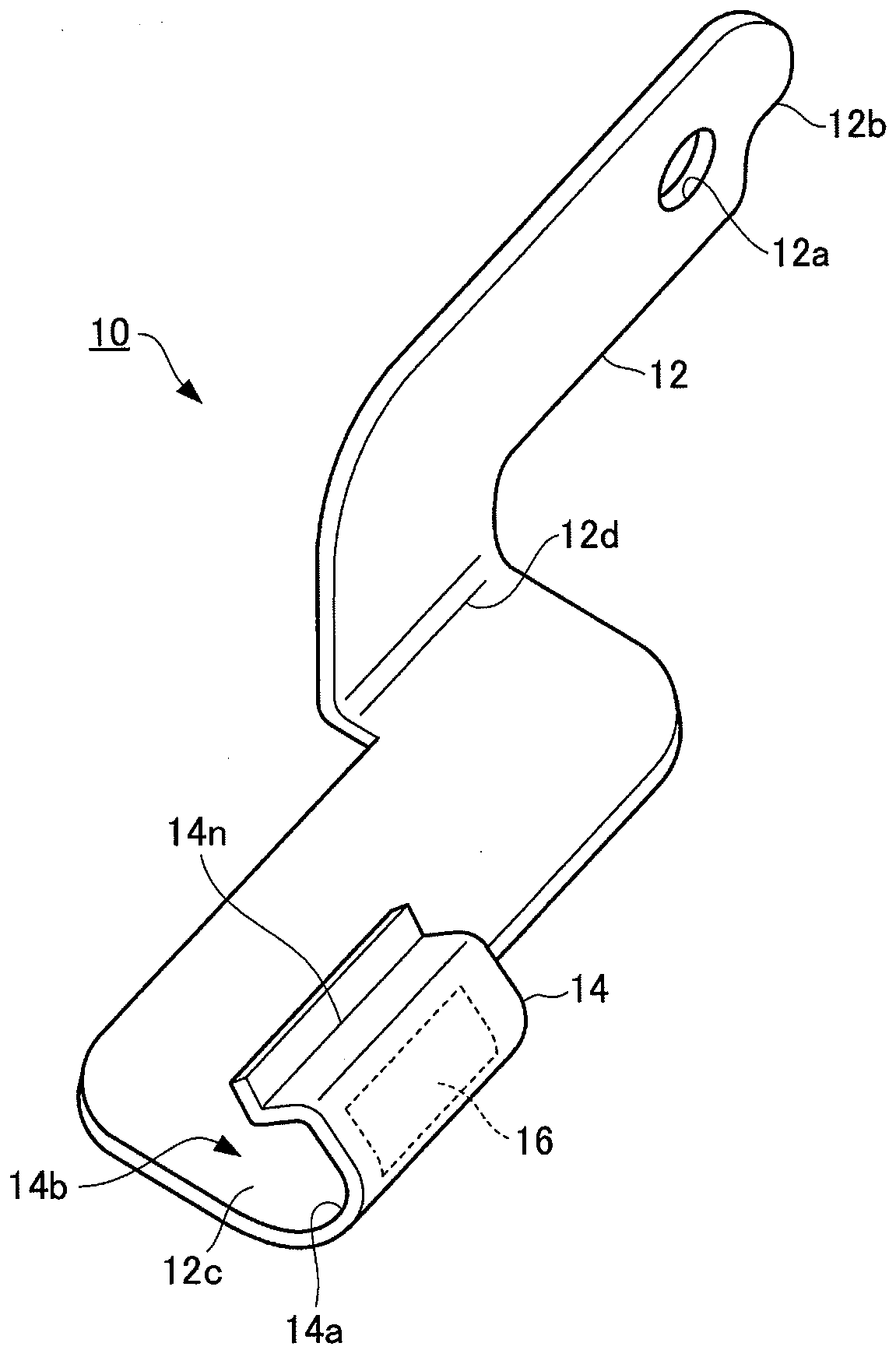
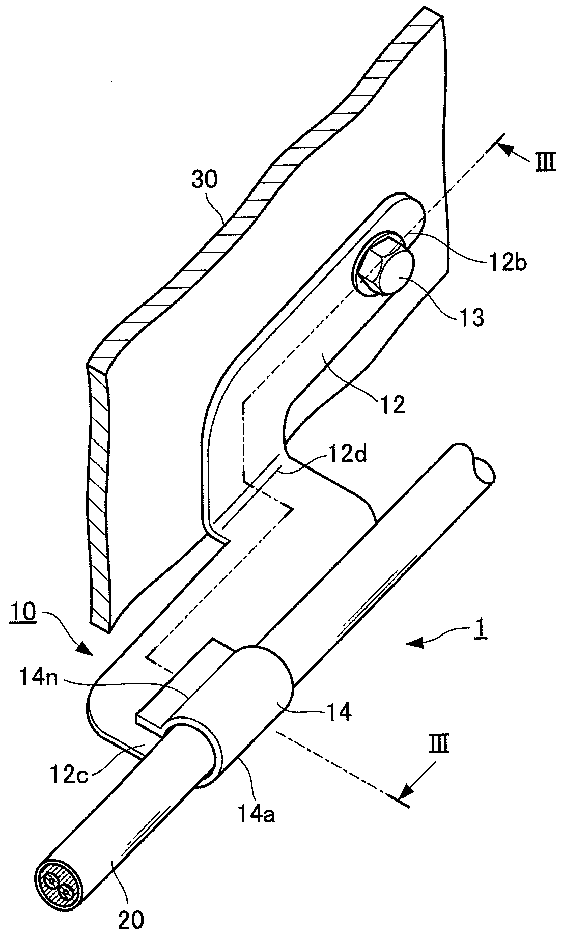
[0029]An electric wire holder 10 according to a first embodiment is configured to hold an electric wire 20 to be routed to an EPB of an automobile and to be fixed to a support panel 30, which is a support on a vehicle body side. Specifically, as shown in FIGS. 1 and 2, the electric wire holder 10 according to this embodiment includes a fixed portion 12 to be fixed to the support panel 30 provided on the vehicle body, and a holding portion 14 that extends from one end 12c of the fixed portion 12 and is configured to hold the electric wire 20 to be routed to an EPB. The electric wire holder 10 can be manufactured by punching, bending, or drilling a metal plate, for example.
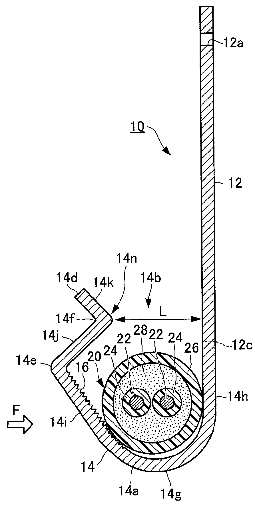
[0030]As shown in FIGS. 3A and 3B, the electric wire 20 for an EPB has a configuration in which two core wires 22 that are each coated with an inner insulating coating material 24 made of polyethylene, for example, are surrounded by a relatively thick outer insulating coating material 26 made of polyurethane, for ex...
second embodiment
[0046]Next, an electric wire holder according to a second embodiment of the present invention will be described.
[0047]The electric wire holder according to the second embodiment has configurations similar to those of the above-described electric wire holder 10 according to the first embodiment other than the configuration of the serration 16, and therefore, description of the similar configurations will be omitted.
[0048]FIG. 5A is a developed view of the holding portion 14, and FIG. 5B is a cross-sectional view taken along line V-V in FIG. 5A. As shown in FIGS. 5A and 5B, a serration 17 according to this embodiment includes grooves 17a forming a lattice. The grooves 17a forming a lattice are formed on the inner surface of the second flat portion 14i of the holding portion 14 over the entire width thereof. The number of the grooves 17a, the pitches between the grooves, the length, width, and depth of each of the grooves 17a, and the like can be set as desired in accordance with a mag...
third embodiment
[0051]Next, an electric wire holder according to a third embodiment of the present invention will be described.
[0052]The electric wire holder according to the third embodiment has configurations similar to those of the above-described electric wire holder 10 according to the first embodiment except the configuration of a serration 18, and therefore, description of the similar configurations will be omitted.
[0053]FIG. 6A is a developed view of the holding portion 14, FIG. 6B is a cross-sectional view taken along line VI-VI in FIG. 6A, and FIG. 6C is a cross-sectional view taken along line VII-VII. As shown in FIGS. 6A to 6C, the serration 18 according to this embodiment is provided with a plurality of triangular holes 18a, and projections 18b that rise from edges of the holes 18a. The plurality of triangular holes 18a are formed on the inner surface of the second flat portion 14i over the entire width thereof. The number of the holes 18a, the pitches between the holes, the size of ea...
PUM
 Abstract
Description
Claims
Application Information
 - R&D Engineer
- R&D Manager
- IP Professional
- Industry Leading Data Capabilities
- Powerful AI technology
- Patent DNA Extraction
Browse by: Latest US Patents, China's latest patents, Technical Efficacy Thesaurus, Application Domain, Technology Topic.
© 2024 PatSnap. All rights reserved.Legal|Privacy policy|Modern Slavery Act Transparency Statement|Sitemap