Fuel evaporative emission control device

a technology of evaporative emission control and purge control, which is applied in the direction of electrical control, machines/engines, mechanical equipment, etc., can solve the problems of not desirable in terms of durability of sealing valve and power consumption, and the execution of tank purge over a long period of time is not desirable in terms of fuel efficiency, so as to suppress the effect of fuel consumption and the operation time of the internal combustion engin

Active Publication Date: 2018-04-19
MITSUBISHI MOTORS CORP
View PDF12 Cites 2 Cited by
  • Summary
  • Abstract
  • Description
  • Claims
  • Application Information

AI Technical Summary

Benefits of technology

[0010]Accordingly, the present invention has its object to provide a fuel evaporative emission control device which is capable of protecting the sealing valve by suppressing execution of tank purge over a long period of time.
[0012]Therefore, according to the fuel evaporative emission control device of the present invention, restriction of operation of the sealing valve is performed based on an operation state of the canister opening / closing valve that is closed upon determination of start of tank purge, and execution of tank purge over a long period of time may be suppressed, and the sealing valve may be restricted from being open for a long period of time, and thus the sealing valve may be protected.

Problems solved by technology

In such a case, tank purge is performed for a long period of time, and the sealing valve is kept open for a long period of time, and this is not desirable in terms of durability of the sealing valve and power consumption.
Accordingly, execution of tank purge over a long period of time is not desirable also in terms of fuel efficiency.

Method used


Image

  • Fuel evaporative emission control device
  • Fuel evaporative emission control device
  • Fuel evaporative emission control device

Examples


Embodiment Construction

[0024]Hereinafter, an embodiment of the present invention will be described with reference to the drawings.

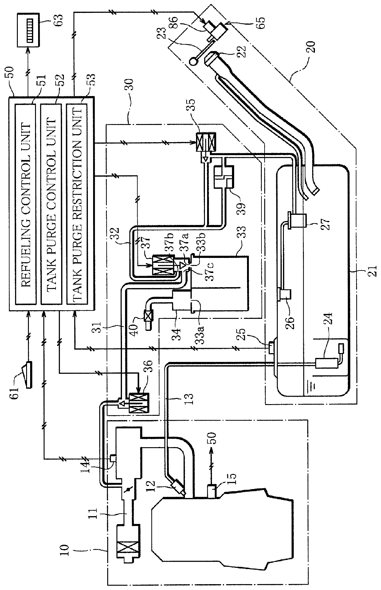
[0025]FIG. 1 is a schematic configuration diagram of a fuel evaporative emission control device 1 according to an embodiment of the present invention.

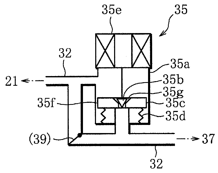
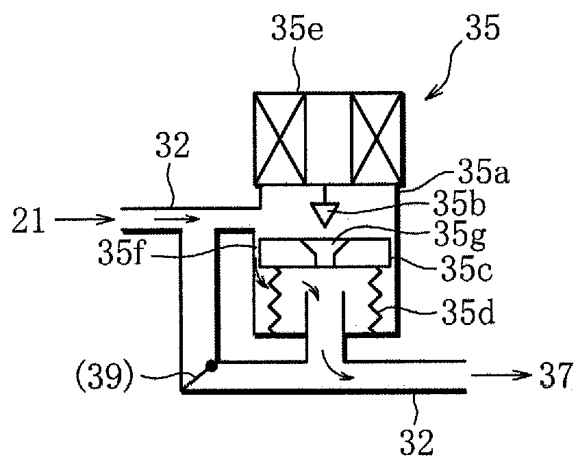
[0026]Also, FIGS. 2 to 4 are explanatory diagrams showing the structure and operation of a sealing valve 35, and FIG. 2 shows a non-energized state, FIG. 3 shows an energized state where the pressure is higher on a fuel tank side than on a bypass valve side, and FIG. 4 shows an energized state where the pressure is substantially the same on the fuel tank side and the bypass valve side. FIGS. 5 and 6 are explanatory diagrams showing the structure and operation of an evaporative leak check module, and FIG. 5 shows a state where a switching valve is not operated, and FIG. 6 shows a state where the switching valve is operated. Solid arrows in FIGS. 2 to 4 indicate the flow direction of fuel evaporative gas. Arrows in FIGS. 5 and 6 ind...


PUM


Abstract

A fuel evaporative emission control device including an electronic control unit that, when fuel tank inner pressure exceeds a first predetermined pressure, performs tank purge of closing a bypass valve and opening a sealing valve, discharging fuel evaporative gas inside the fuel tank into an air intake path of an engine in an operated state through a purge pipe and a vapor pipe, and treating the fuel evaporative gas, where, when tank purge is performed, if a first predetermined period of time passes after closing of the bypass valve without the fuel tank inner pressure falling to or below the first predetermined pressure, the sealing valve is closed and tank purge is stopped.

Description

CROSS-REFERENCE TO RELATED APPLICATIONS[0001]This application is a Divisional of copending application Ser. No. 15 / 188,094, filed on Jun. 21, 2016, which claims priority under 35 U.S.C. § 119(a) to Application No. 2015-124812, filed in Japan on Jun. 22, 2015, all of which are hereby expressly incorporated by reference into the present application.FIELD OF THE INVENTION[0002]The present invention relates to a purge control technique of a fuel evaporative emission control device.DESCRIPTION OF THE RELATED ART[0003]In order to prevent fuel evaporative gas vaporized inside a fuel tank from being discharged outside at the time of refueling, many vehicles are conventionally provided with a fuel evaporative emission control device including a canister that is disposed on a communication path communicating between the fuel tank and an air intake path of an internal combustion engine, a sealing valve (a tank blocking valve) for communicating or blocking between the fuel tank and the canister...

Claims


Application Information

Patent Timeline
Patent Type & Authority Applications(United States)
IPC IPC(8): F02D41/00F02M25/08
CPCF02D2200/0602F02M2025/0845F02M25/08F02D41/0032F02M25/0854F02M25/0836F02M25/0872
Inventor WAKAMATSU, ATSUSHIKUNII, KENICHI
Owner MITSUBISHI MOTORS CORP
Why Eureka
Try Eureka