Cleaning appliance

Active Publication Date: 2018-04-26
DYSON TECH LTD
View PDF7 Cites 19 Cited by
  • Summary
  • Abstract
  • Description
  • Claims
  • Application Information

AI Technical Summary

Benefits of technology

[0024]To facilitate the movement of the nozzle along the teeth of user during use of the appliance, the head preferably comprises means, spaced from the nozzle, for engaging the teeth of the user. For user comfort, the engaging means

Problems solved by technology

When the handle is being gripped by a user during use of the appliance, the illuminated LEDs may

Method used


Image

  • Cleaning appliance
  • Cleaning appliance
  • Cleaning appliance

Examples


Embodiment Construction

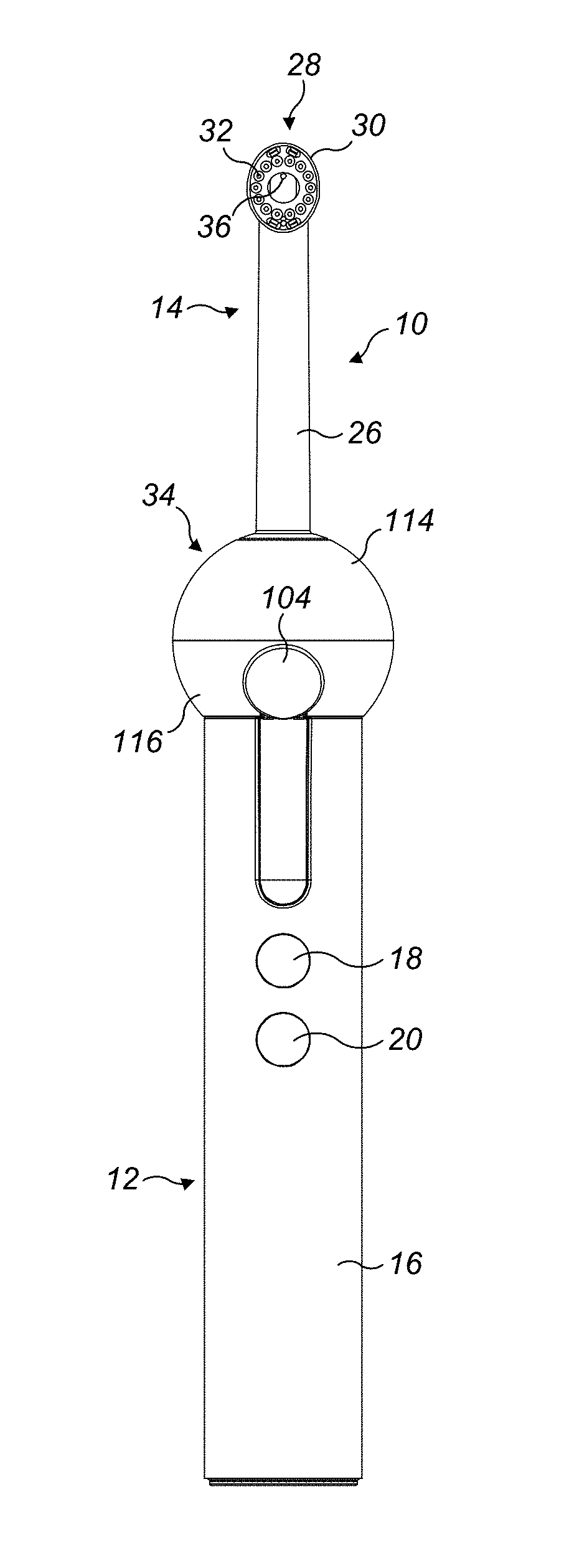
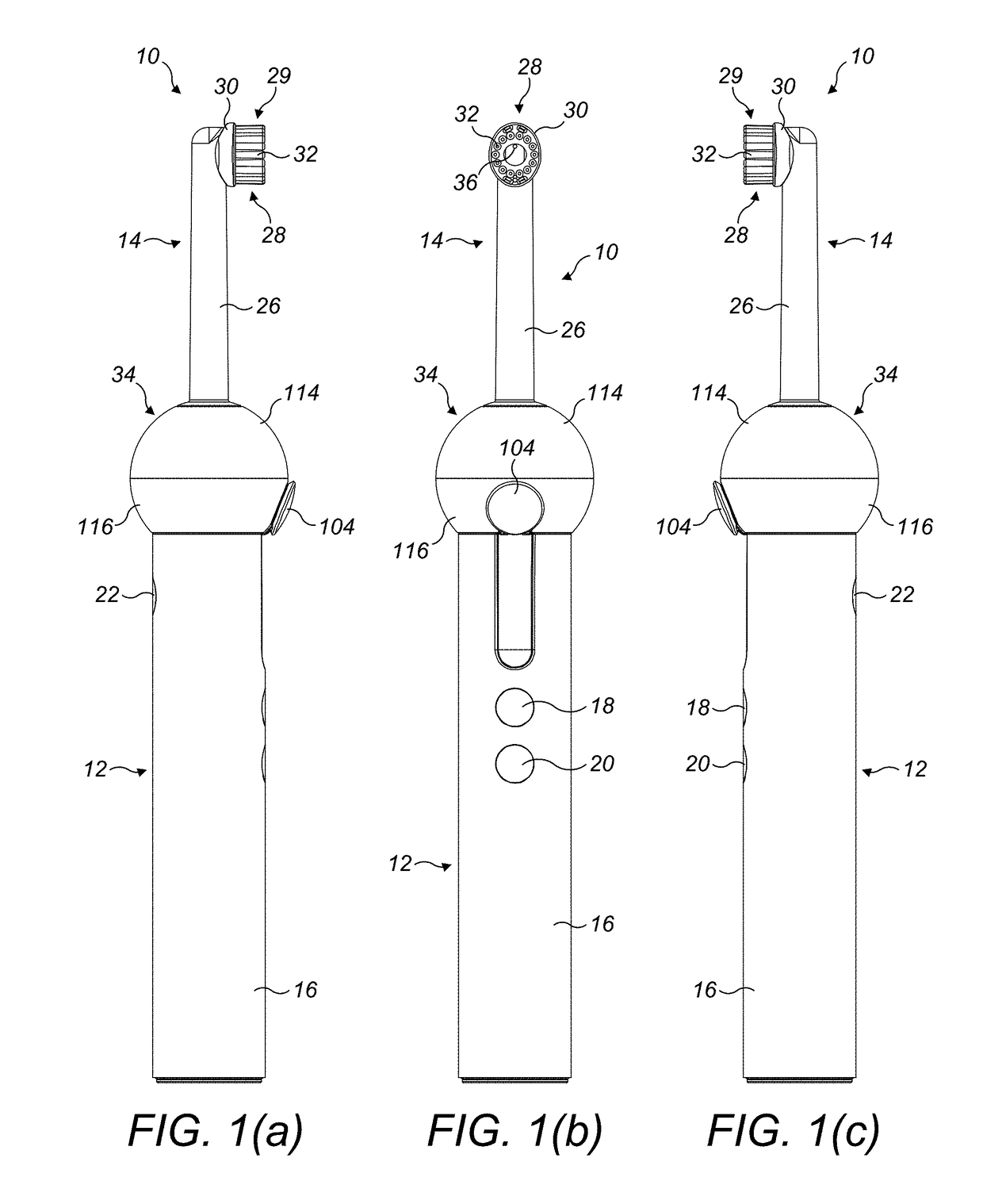
[0040]FIGS. 1(a) to 1(c) illustrate external views of an embodiment of a dental cleaning appliance 10. In this embodiment, the appliance is in the form of a handheld appliance, which is in the form of an electric toothbrush having an integrated assembly for dispensing a working fluid for improved interproximal cleaning.

[0041]The appliance 10 comprises a handle 12 and a cleaning tool 14. The handle 12 comprises an external body 16 which is gripped by a user during use of the appliance 10. The body 16 is preferably formed from plastics material, and is preferably generally cylindrical in shape. The handle 12 comprises a plurality of user operable buttons 18, 20, 22 which are located within respective apertures formed in the body 16 so as to be accessible to the user. The handle 12 may comprise a display which is positioned so as to be visible to a user during use of the appliance.

[0042]The cleaning tool 14 comprises a stem 26 and a head 28. The stem 26 is elongate in shape, which serv...


PUM


Abstract

A dental cleaning appliance includes a fluid reservoir for storing working fluid, a nozzle for delivering working fluid to the teeth of a user, a light source for illuminating the fluid reservoir and a control circuit for activating the light source to generate an alert which is conveyed to the user through the illumination of the fluid reservoir.

Description

REFERENCE TO RELATED APPLICATIONS[0001]This application claims the priority of United Kingdom Application No. 1618073.9, filed Oct. 26, 2016, the entire contents of which are incorporated herein by reference.FIELD OF THE INVENTION[0002]The present invention relates to a cleaning appliance. The cleaning appliance is preferably a handheld cleaning appliance, and is preferably a surface treating appliance. In preferred embodiments of the invention, the appliance is a dental cleaning appliance. In a preferred embodiment, the appliance is an electric toothbrush having a fluid delivery system for delivering a fluid to the teeth of the user. This fluid may be toothpaste, or a fluid for improved interproximal cleaning. Alternatively, the appliance may not include any bristles or other elements for brushing teeth, and may be in the form of a dedicated interproximal cleaning appliance. The invention also relates to a cleaning tool for use with a dental cleaning appliance, and to a handle for ...

Claims


Application Information

Patent Timeline
IPC IPC(8): A61C17/22A61C17/36A46B13/04A61C17/28A46B15/00
CPCA61C17/227A61C17/36A46B13/04A61C17/28A46B15/0044A46B15/0036A46B15/0004A46B2200/1066A46B15/0034A46B11/001A46B13/02A46B15/0012A46B11/0062A61C17/0202A61C17/222A61C1/088A61C17/028A61C17/221
Inventor MIGHALL, SCOTT JAMESVINCENT, CHRISTOPHER GRAHAMMARSH, JONATHAN GEORGEHARRIS, SAMMANTHA STEPHANIEZUKINA, BORISPROBERT, MICHAEL GRAHAMWILKINSON, CHRISTOPHER DANIEL CURRER
Owner DYSON TECH LTD
Why Eureka
Try Eureka