Control apparatus, robot, and robot system

Active Publication Date: 2018-04-26
SEIKO EPSON CORP
View PDF4 Cites 10 Cited by
  • Summary
  • Abstract
  • Description
  • Claims
  • Application Information

AI Technical Summary

Benefits of technology

[0005]An advantage of some aspects of the invention is to solve at least a part of the problems de

Problems solved by technology

However, in the robot described in Patent Document 1, the two robot arms are moved (operated) by position control at work, and it is difficult to synchronize the two robot arms with each other.
Accordingly, in the case of wo

Method used


Image

  • Control apparatus, robot, and robot system
  • Control apparatus, robot, and robot system
  • Control apparatus, robot, and robot system

Examples


Example

[0033]As below, a control apparatus, a robot, and a robot system according to the invention will be explained in detail based on embodiments shown in the accompanying drawings.

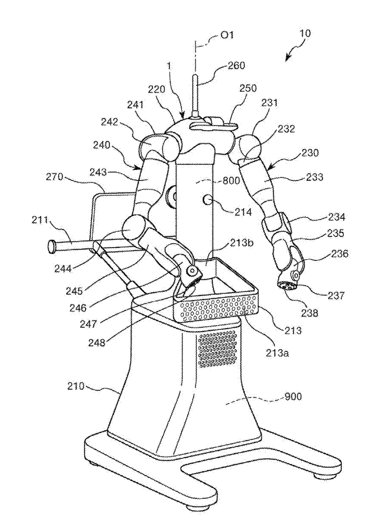
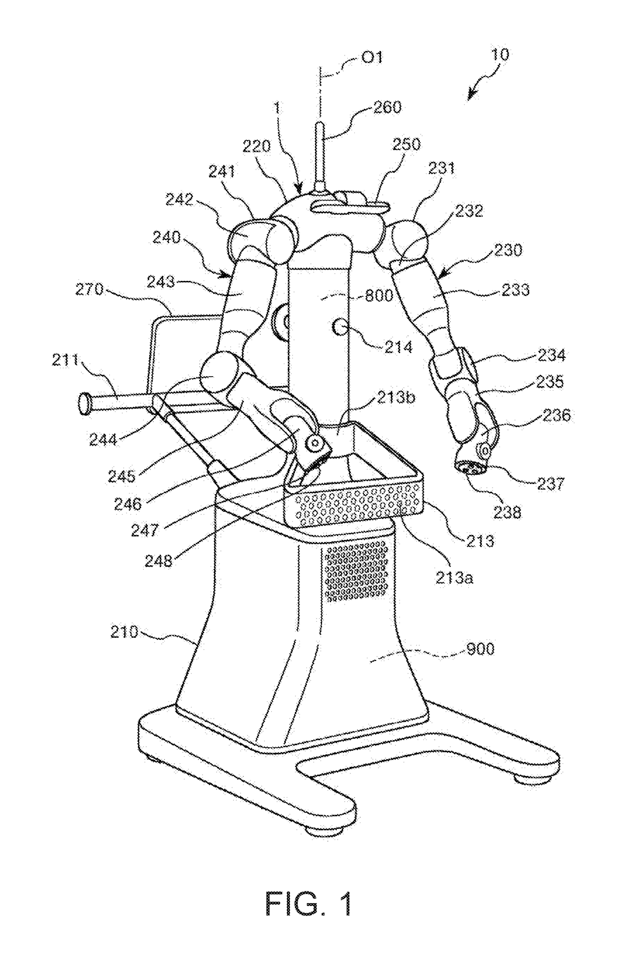
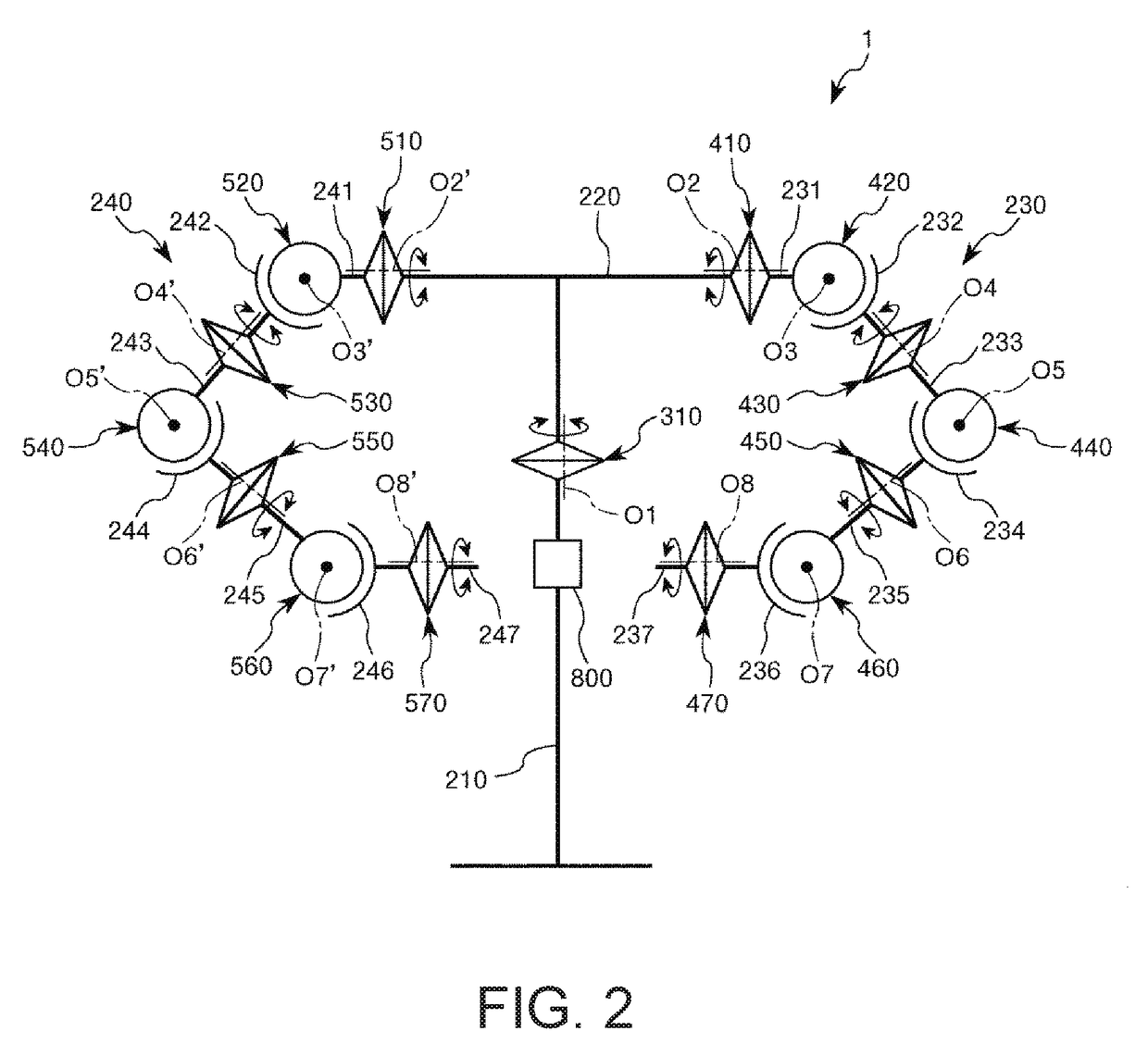
[0034]FIG. 1 is a perspective view showing an embodiment of a robot system according to the invention. FIG. 2 is a schematic diagram of a robot of the robot system shown in FIG. 1. FIG. 3 shows end effectors and force sensors attached to the robot of the robot system shown in FIG. 1. FIG. 4 is a block diagram of a main part of the robot system shown in FIG. 1. FIG. 5 is a flowchart showing a control operation of a control apparatus of the robot system shown in FIG. 1. FIGS. 6 to 12 are diagrams for explanation of an operation of the robot of the robot system shown in FIG. 1.

[0035]Hereinafter, for convenience of explanation, the upside in FIGS. 1 and 6 to 12 is referred to as “upper” or “above” the downside is referred to as “lower” or “below”. The base side in FIGS. 1 and 6 to 12 is referred to as “proximal en...


PUM


Abstract

A control apparatus that controls a first robot arm provided with a first force detection part and a second robot arm provided with a second force detection part, includes a processor that configured to move the first robot arm until a target force is detected by the first force detection part and performs impedance control on the second robot arm based on output of the second force detection part in at least a part of a movement period in which the first robot arm is moved.

Description

BACKGROUND1. Technical Field[0001]The present invention relates to a control apparatus, a robot, and a robot system.2. Related Art[0002]Robots each including a base and a robot arm having a plurality of arms (links) are known. One arm of two adjacent arms of the robot arm is rotatably coupled to the other arm via a joint part, and the arm on the most proximal end side (on the most upstream side) is rotatably coupled to the base via a joint part. The joint parts are driven by motors and the arms rotate by the driving of the joint parts. Further, as an end effector, e.g. a hand or the like is detachably attached to the arm on the most distal end side (on the most downstream side). For example, the robot grasps an object with the hand, moves the object to a predetermined location, and performs predetermined work such as assembly.[0003]Patent Document 1 (JP-A-2010-23128) discloses a dual-arm robot including two robot arms (first robot, second robot). In the robot described in Patent Doc...

Claims


Application Information

Patent Timeline
IPC IPC(8): B25J9/16B25J13/08
CPCB25J9/1682B25J13/085B25J9/1633G05B2219/45048B25J9/0087G05B2219/39109G05B2219/39343
Inventor HASEGAWA, FUMIAKIOKADA, RYUICHI
Owner SEIKO EPSON CORP
Why Eureka
Try Eureka