Camera shake correction device and imaging apparatus having the same

a technology of camera shake and correction device, which is applied in the field of camera shake correction device and imaging apparatus, can solve the problems of inaccurate camera shake detection and inability to perform camera shake correction accurately, and achieve the effects of eliminating uneven distribution of charges in capacitors and uneven distribution of charges

Inactive Publication Date: 2008-04-08
SONY CORP
View PDF13 Cites 10 Cited by
  • Summary
  • Abstract
  • Description
  • Claims
  • Application Information

AI Technical Summary

Benefits of technology

[0027]Accordingly, the present invention has been conceived so as to enable a camera shake correction device to accurately and quickly perform camera shake correction by resetting, when it is detected that panning or tilting is taken place, charges accumulated in the capacitor constituting the high-pass filter to thereby eliminate irregular distribution of charges in the capacitor.
[0039]According to another preferred embodiment of the second apparatus, the switching means constituting this camera shake correction device may charge the capacitor to- the reference voltage by turning the switch on when a power supply is turned on.
[0041]Thus, when it is detected according to an output signal of the sensor for detecting movement of the camera body that a panning or a tilting is taken place, it is decided whether or not electric charges accumulated in the capacitor of the high-pass filter are unevenly distributed therein. In a case where the accumulated electric charges are unevenly distributed therein, the capacitor is discharged to the reference voltage. Thus, the unevenness of the distribution of the charges in the capacitor is eliminated. Consequently, a process to be performed by the apparatus can immediately be changed to camera shake correction.

Problems solved by technology

However, when performing panning or tilting, the level of the signal remains at one of upper and lower limit values of a sensor output voltage.
In this sense, conventional camera shake correction devices have drawbacks in that, needless to say, a camera shake cannot accurately be detected under such condition, and that camera shake correction cannot be performed accurately.

Method used


Image

  • Camera shake correction device and imaging apparatus having the same
  • Camera shake correction device and imaging apparatus having the same
  • Camera shake correction device and imaging apparatus having the same

Examples


Embodiment Construction

[0051]Hereinafter, preferred embodiments of a camera shake correction device and an imaging apparatus having this camera-shake correction device according to the present invention will be described in detail by referring to the accompanying drawings, in which an angular sensor is used as means for detecting movement of a camera body and in which a method of driving part of an optical system and changing an optical axis thereof is used in an image controlling section,.

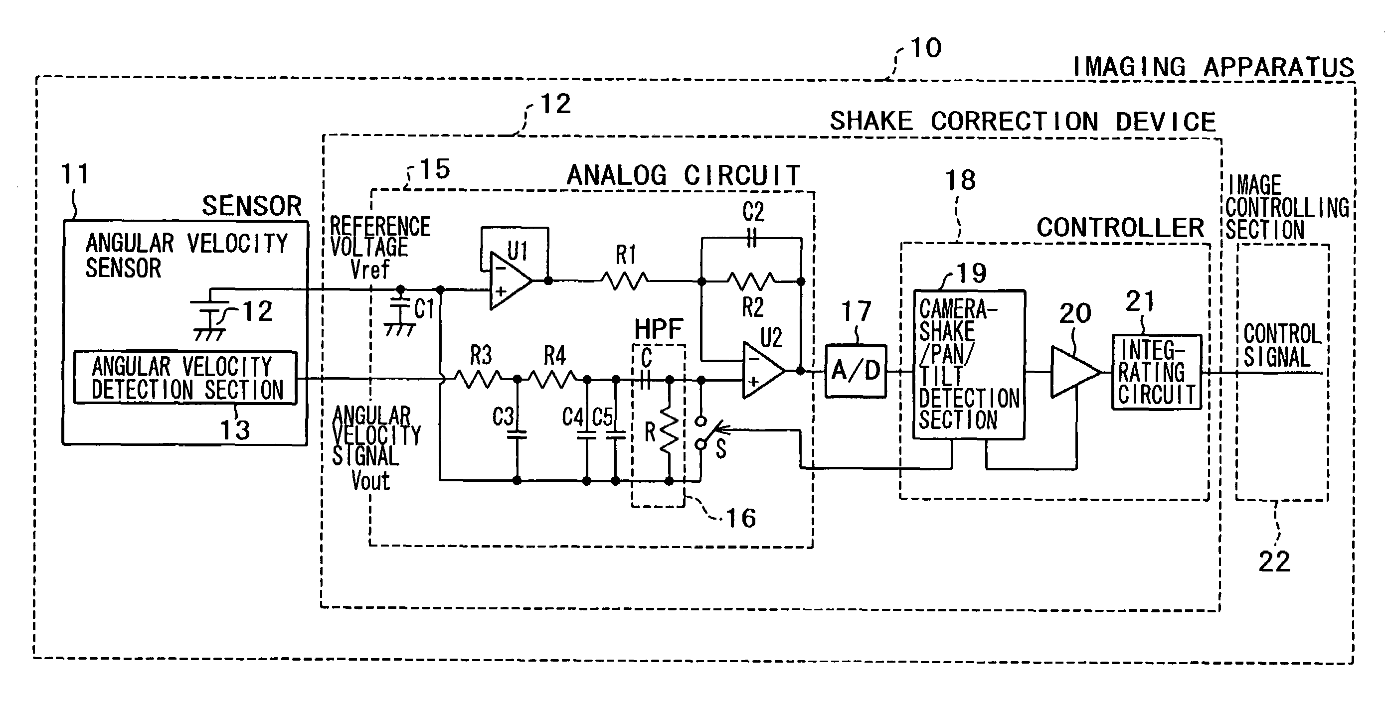
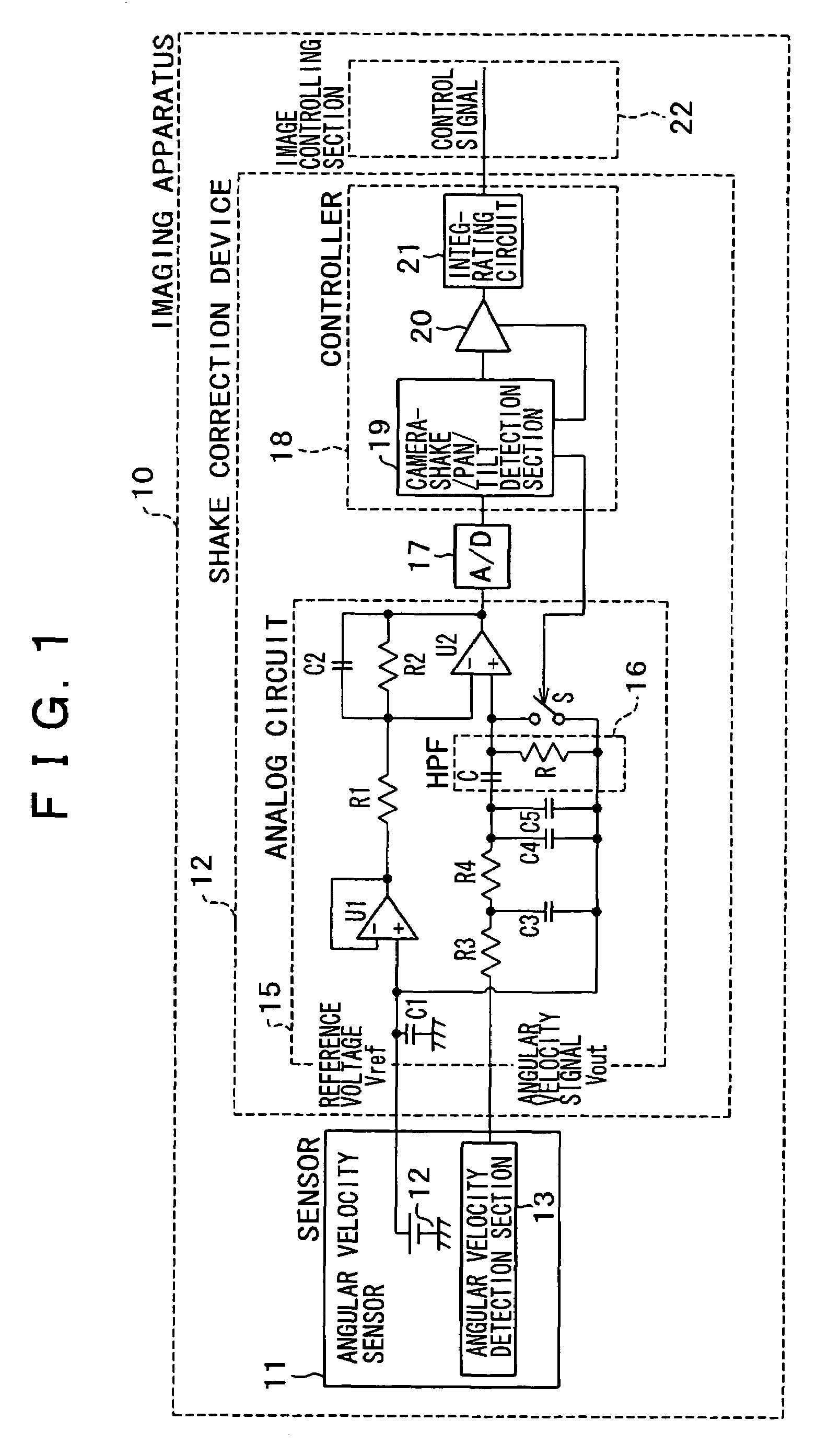
[0052]As shown in FIG. 1, an imaging apparatus having a camera shake correction device according to a preferred embodiment of the present invention has a sensor section 11, a camera shake correction device 12, and an image controlling section 22. The sensor section 11 has an angular velocity detection section 13 attached to a casing of a camera body. The camera shake correction device 12 detects panning / tilting according to an output signal (an angular velocity signal) Vout of the sensor section 11 and a reference volta...


PUM


Abstract

The present invention provides a camera shake correction device enabled to quickly correct a camera shake. This device has a sensor for detecting movement of a camera, a high-pass filter, an amplifier, an A / D converter, a camera-shake / pan / tilt detection unit, and a switching unit. The filter includes a circuit having a capacitor and a resistor connected in series. A reference voltage is inputted to a common ground terminal of the circuit. An output signal of the sensor is amplified by the amplifier. The A / D converter converts the amplified signal into a digital value. The detection unit detects a camera shake or panning / tilting according to the digital value. When detected, the switching unit turns on a switch connected to the resistor so as to discharge the capacitor to the reference voltage.

Description

CROSS REFERENCE TO RELATED APPLICATIONS[0001]The present document is based on Japanese Priority Application JP2003-002593, filed in the Japanese Patent Office on Jan. 8, 2003, the contents of which being incorporated herein by reference to the extent permitted by law.BACKGROUND OF THE INVENTION[0002]1. Field of the Invention[0003]The present invention relates generally to a camera shake correction device and an imaging apparatus having this camera shake correction device. More particularly, the present invention relates to a camera shake correction device for use in an imaging apparatus having a camera shake correcting function, which is improved in such a way as to be able to quickly perform the camera shake correcting function when detecting panning or tilting, and also relates to an imaging apparatus having this camera shake correction device.[0004]2. Description of the Related Art[0005]As shown in FIG. 6, an imaging apparatus having a conventional camera shake correction device ...

Claims


Application Information

Patent Timeline
Patent Type & Authority Patents(United States)
IPC IPC(8): H04N5/228H04N5/232
CPCG01C19/5776H04N5/23287H04N5/23258H04N5/23248H04N23/68H04N23/6812H04N23/687
Inventor KUMAKI, JINYO
Owner SONY CORP
Why Eureka
Try Eureka