Hand-Held Tool System

a tool system and hand-held technology, applied in the field of hand-held tool systems, can solve the problems of time-consuming and energy-consuming, easy deviation of position and the like, complex operations, etc., and achieve the effect of accurate and rapid positioning

Active Publication Date: 2019-09-19
POSITEC POWER TOOLS (SUZHOU) CO LTD
View PDF0 Cites 9 Cited by
  • Summary
  • Abstract
  • Description
  • Claims
  • Application Information

AI Technical Summary

Benefits of technology

[0172]The beneficial effect of the above technical solutions of the present invention is that in the process that the positioning device is moved, the distance between the position

Problems solved by technology

Operations are complex, time-consuming and energy-consuming, traces may be left on the wall or the workpiece.
Moreover, since overall layout is not conducted bef

Method used


Image

  • Hand-Held Tool System
  • Hand-Held Tool System
  • Hand-Held Tool System

Examples


first embodiment

A First Embodiment

[0244]A positioning apparatus and a hand-held tool system equipped with the positioning apparatus of the present invention will be described below in detail in combination with specific embodiments.

[0245]In the hand-held tool system involved in the present invention, the hand-held tool is preferably a drilling tool; a hand-held tool for positioning, such as an electric drill, a screwdriver, an impact wrench; and an electric hammer, or a hand-held for cutting a workpiece, such as an electric circular saw, a reciprocating saw, and a chain saw.

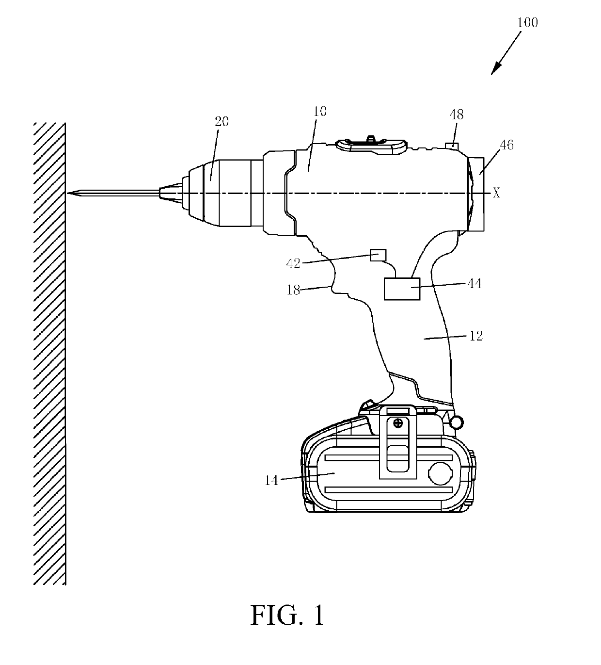
[0246]FIG. 1 is a schematic structural diagram of an electric drill. The electric drill includes: a horizontally arranged main body portion; a holding portion arranged at an angle to the main body portion, that is, a handle 12; and a battery pack 14 detachably connected to the handle at the bottom of the handle. A housing 10 of the main body portion is provided with a motor (not shown) and an output shaft (not shown) that is dri...

second embodiment

A Second Embodiment

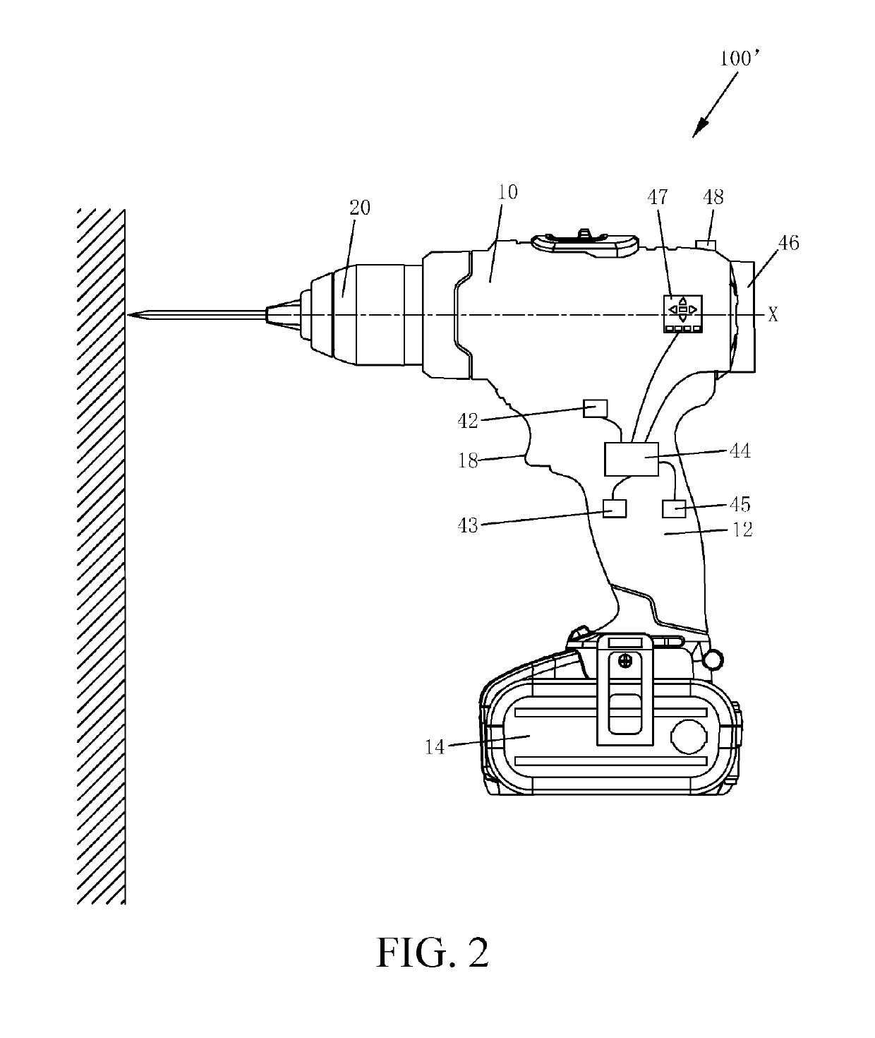
[0256]FIG. 2 is a schematic diagram of another electric drill. The ranging and positioning apparatus includes an input unit for setting a position parameter relative to the reference position, that is, predetermined position information, and inputting a predetermined position via a keyboard, a touch screen, or a button, preferably a keyboard. The user may input the moving distance as needed. Then, the user may actuate the positioning mode key at the reference position and move the electric drill. When the electric drill reaches a specified position, the user may be prompted correspondingly in a sensible manner, for example, by blinking of an LED lamp of the display screen, or by sound production of a buzzer 43 as long as the ranging and positioning apparatus further includes the buzzer 43, or by vibration or other ways that can be perceived in visual sense, auditory sense, or tactile sense. The sensible manner includes but not limited to optical and / or acoustic an...

third embodiment

A Third Embodiment

[0278]Referring to FIG. 13, the ranging and positioning apparatus 30 of this embodiment is combined with the electric drill 100a into one. The electric drill 100a includes a body 11. The body 11 includes a main body portion and a handle 12 at an angle to the main body portion and providing a holding operation. The ranging and positioning apparatus 30 is mounted on the main body portion of the body 11. A power motor (not shown) is arranged on the body 11. The handle 12 includes a switch trigger 13 configured to control the motor. A tail end, extending along an axis, of the handle 12 is connected to a battery pack 14. The ranging and positioning apparatus 30 of the embodiments of the present invention is configured to be integrated into the body 11. A person skilled in the art would envisage that the ranging and positioning apparatus 30 may also be designed individually as a module, and then, detachably mounted on the body 11 in the form of an accessory.

[0279]The ran...


PUM


Abstract

A hand-held tool system comprises a hand-held tool and a positioning device matching the hand-held tool. The hand-held tool comprises an output shaft and a working head coupled to the output shaft. The positioning device comprises a detecting module configured to detect a positional feature and/or a movement feature of the positioning device and output a parameter indicative of the positional feature and/or the movement feature, the detecting module and the working head having a preset distance therebetween; a storage module configured at least to record reference position information about the working head; a control module configured to acquire real-time position information about the working head based on the parameter, the preset distance and the reference position information; and an output module configured to output the real-time position information in a way that can be perceived.

Description

BACKGROUNDTechnical Field[0001]The present invention relates to a hand-held tool system, and in particular, to a hand-held tool system provided with a positioning device.Related Art[0002]Currently, during punching holes continuously or mounting screws on a workpiece by using a hand-held tool, such as an electric screwdriver and a hand-held electric drill, so as to hang pictures on a wall, in order to ensure that various punching points are arranged based on specified distances and directions, pre-measurement, lineation, and working point position marking need to be performed in advance. Operations are complex, time-consuming and energy-consuming, traces may be left on the wall or the workpiece. Moreover, since overall layout is not conducted before hanging the pictures, positions between picture frames are discordant or a spacing is not suitable, so that position deviation and the like may occur easily.[0003]In view of this, it is necessary to research and develop a hand-held tool s...

Claims


Application Information

Patent Timeline
IPC IPC(8): B23Q17/22G01S17/08G01P15/18G01C9/00B23Q9/00B23Q16/00
CPCB23Q2716/00B23Q16/00B23Q9/0071G01P15/18B23Q17/22G01S17/08G01C9/00B23Q2717/00B25H1/00G06T5/00G01S17/88G01S17/87B23B2260/128B23B2260/092B23B49/00
Inventor SHAO, YONGWU, JUNHE, MINGMINGANDRIOLO, PAOLOWONG, KA TAT KELVINMENG, SHUAI
Owner POSITEC POWER TOOLS (SUZHOU) CO LTD
Why Eureka
Try Eureka