Stent delivery system, corresponding flow diversion device, and assembly method of flow diversion device

Active Publication Date: 2018-05-10
ACCUMEDICAL BEIJING LTD
View PDF1 Cites 53 Cited by
  • Summary
  • Abstract
  • Description
  • Claims
  • Application Information

AI Technical Summary

Benefits of technology

[0032]The devices described above can be used for aneurysm treatment, wherein the stent is easily released and may be retrieved. Said devices may reduce risks in interventional surgeries, as well as rejection rate of expensive medical equipments, thereby improving the success rate

Problems solved by technology

The wall of an aneurysm is thin and fragile, making it prone to rupturing.
However, at least the following defects exist when the interventional embolization treatment mentioned above is adopted for large (maximum diameter of more than 10 mm) or huge (maximum diameter of more than 25 mm) aneurysms.
First, it is required to use embolic materials such as coils to densely fill the aneurysm.
However, large or huge aneurysms are often wide-necked aneurysms.
In such cases, coils as the embolus are very easy to project out into the parent artery carrying the aneurysms, which may cause stenosis or even occlusion to the parent artery.
Taking the cerebral aneurysm as an example, this may lead to serious consequences such as cerebral ischemia or even cerebral infarction.
Second, the mass effect is common to large or huge aneurysms.
The aneurysms may become larger, thereby compressing surrounding viscera and tissues and affecting their physiological functions.
Although filling an aneurysm with coils may embolize the aneurysm, it cannot eliminate the mass effect caused by the aneurysm or may even worsen the mass effect.
After implanted to the parent artery, the flow diversion device may interrupt blood flow from the parent artery to the aneurysm by the f

Method used


Image

  • Stent delivery system, corresponding flow diversion device, and assembly method of flow diversion device
  • Stent delivery system, corresponding flow diversion device, and assembly method of flow diversion device
  • Stent delivery system, corresponding flow diversion device, and assembly method of flow diversion device

Examples


Embodiment Construction

[0040]The following detailed description refers to the accompanying drawings as a part of the present application. The illustrative embodiments described in the detailed description, the accompanying drawings and the claims are not limiting, and other embodiments may be adopted, or modifications may be made without deviating from the spirit and subject of the application. It would be appreciated that the various aspects of the application described and graphically presented herein may be arranged, replaced, combined, divided and designed in many different configurations, and these different configurations are implicitly comprised in the application.

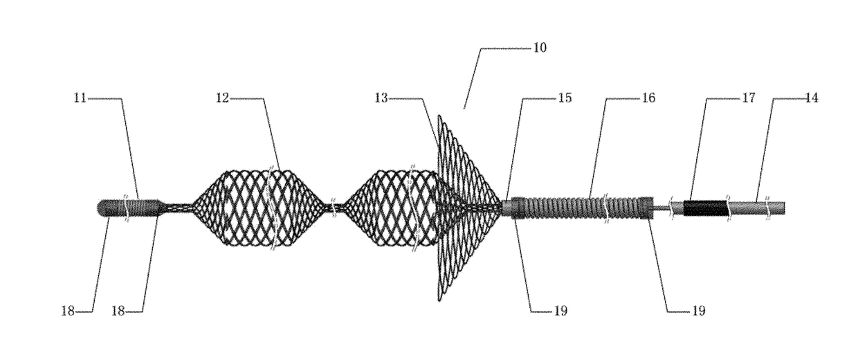
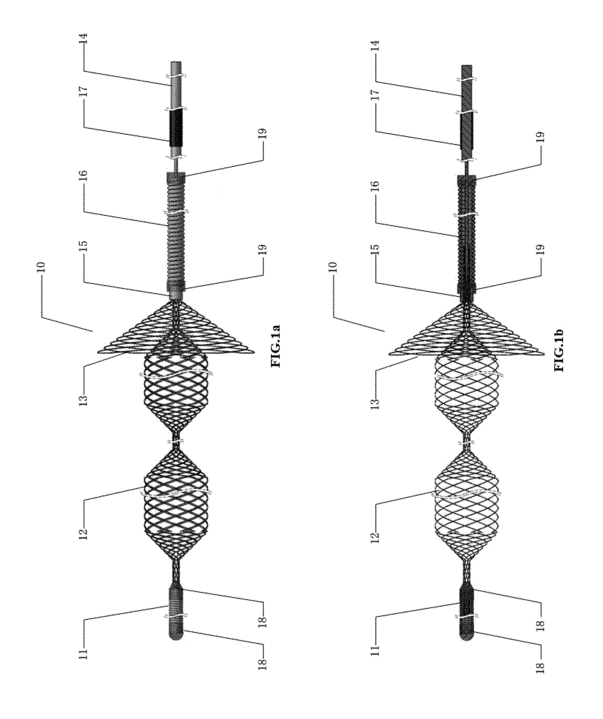
[0041]FIGS. 1a-1b illustrate schematic diagrams of a stent delivery system 10 according to an embodiment of the present application, which may be used to deliver vascular stents having a large metallic surface area and a low void ratio such as the densely-netted stent mentioned above to the target position (e.g. an opened aneurysm). FIG. ...


PUM

PropertyMeasurementUnit
Linear resolutionaaaaaaaaaa
Lengthaaaaaaaaaa

Abstract

A stent delivery system provided by the present application comprises: a radiopaque tip located at the distal end of the stent delivery system; a beads component comprising at least one expandable part; a funnel component comprising a distal flare structure and a proximal collapsed end, wherein the cross-section of the flare structure gradually increases from its minimum diameter to its maximum diameter along the proximal-to-distal direction; and a core wire located at the proximal end of the stent delivery system; and wherein the distal end of the beads component is fixed on the radiopaque tip and the proximal end of the beads component is fixed on the core wire; wherein the funnel component is coupled with the beads component and the core wire, and is fixed on the core wire through the collapsed end. The present application also provides a flow diversion device and an assembly method of the flow diversion device.

Description

CROSS REFERENCE TO RELATED APPLICATIONS[0001]This application claims priority to Chinese Patent Application No. 201610979261.1 filed on Nov. 8, 2016, the entire content of which is incorporated herein by reference.FIELD OF THE INVENTION[0002]The present application relates to the field of intervention therapy, and more specifically, to a stent delivery system as well as a corresponding flow diversion device and an assembly method of flow diversion device.BACKGROUND OF THE INVENTION[0003]A vascular aneurysm is a result of lesion or injury in the arterial wall, which forms a localized or diffuse dilatation or bulge on the arterial wall and mainly shows as an expansile and pulsatile tumor. Aneurysms may occur in any blood vessel and include abdominal aortic aneurysm, cerebral aneurysm, peripheral aneurysm, visceral aneurysm, etc. The wall of an aneurysm is thin and fragile, making it prone to rupturing.[0004]Besides conventional conservative or surgical treatments, the interventional t...

Claims


Application Information

Patent Timeline
IPC IPC(8): A61F2/95B29C65/48
CPCA61F2/95B29C65/4845B29C65/4835A61F2002/9511B29L2031/753A61F2230/0071A61F2230/0086A61F2240/00A61F2250/0098A61F2210/0014A61B17/12118A61B17/1214A61B2017/1205A61F2/966A61F2/958A61F2002/823A61F2002/9534A61F2002/9665
Inventor LU, YIRAN
Owner ACCUMEDICAL BEIJING LTD
Why Eureka
Try Eureka