Control method of shape measuring apparatus

Active Publication Date: 2018-05-31
MITUTOYO CORP
View PDF3 Cites 0 Cited by
  • Summary
  • Abstract
  • Description
  • Claims
  • Application Information

AI Technical Summary

Benefits of technology

The present invention allows for a shape measuring apparatus to continue measuring without stopping, even if the path for scanning measurement is complicated.

Problems solved by technology

However, a measurement site on the work piece has a complicated shape, and to perform a highly accurate scanning measurement while accurately tracking such a measurement site, the number of segments needs to be increased by finely dividing the PCC curve into pieces.
When the number of segments increases, parameters (coefficient of the PCC curve) included in a measurement instruction become enormous as a result.
Therefore, even though the path for scanning measurement is continuous, a measurement command including enormous information (coefficients) can neither be received nor processed all at once.
When the shape measuring apparatus completely stops in the middle of a measurement operation which should be continuous, a user may feel uneasy.
However, such a connection process is complicated.
In addition, when the stop process comes in between, this causes the measurement accuracy to drop, influenced by deceleration or acceleration.

Method used


Image

  • Control method of shape measuring apparatus
  • Control method of shape measuring apparatus
  • Control method of shape measuring apparatus

Examples


first embodiment

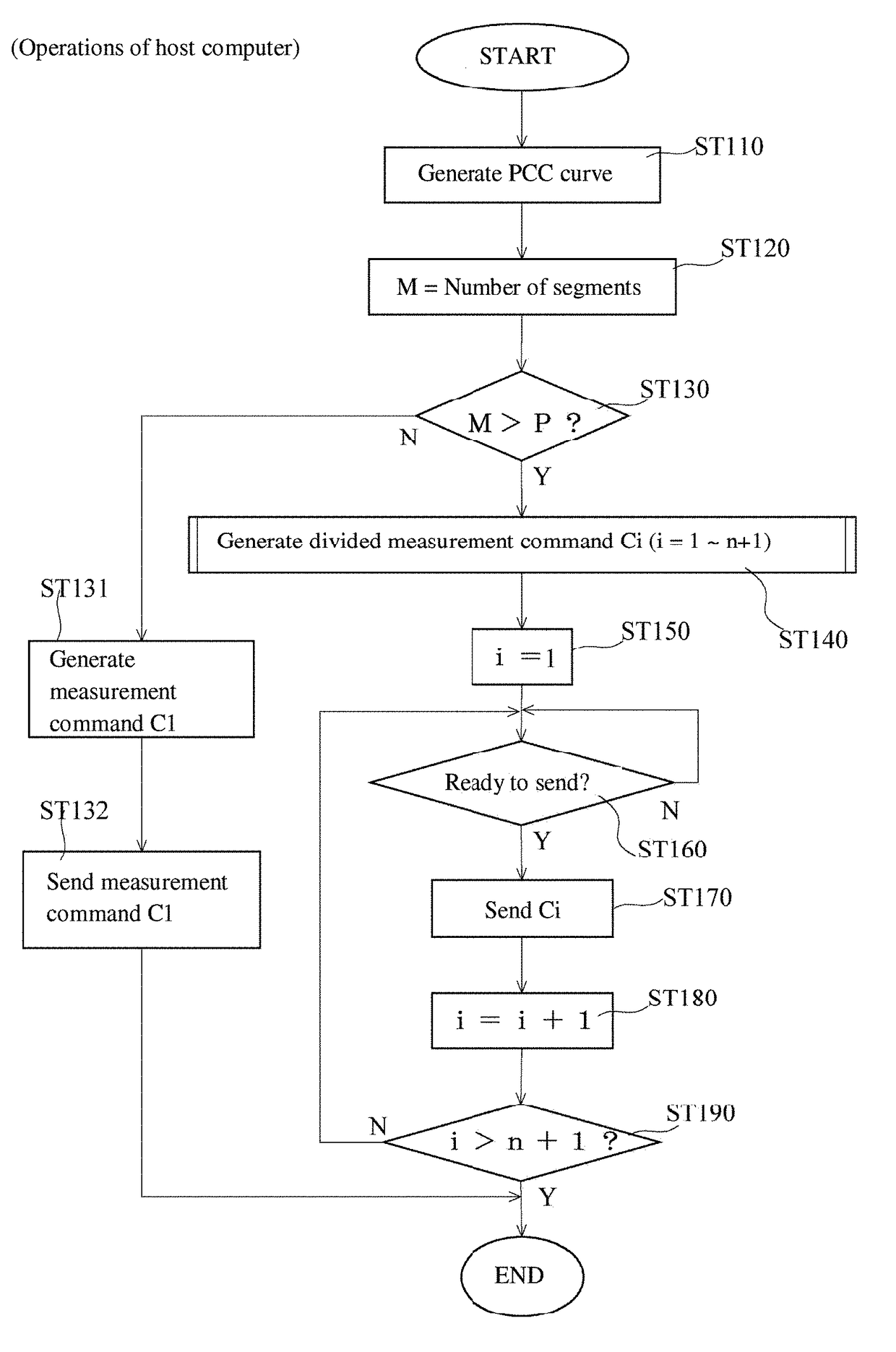
[0052]FIG. 8 illustrates an overall configuration of a shape measurement system 100. The shape measurement system 100 includes a coordinate measuring machine 200, a motion controller 300 controlling activation of the coordinate measuring machine 200, and a host computer 500 controlling the motion controller 300 and executing necessary data processing.

[0053]The coordinate measuring machine 200 includes a stage 210, a displacement mechanism 220, and a probe 230.

[0054]The displacement mechanism 220 includes a gate-shaped Y slider 221 provided so as to be capable of sliding above the stage 210 in a Y direction, an X slider 222 sliding along a beam of the Y slider 221 that lies in an X direction, a Z axis column 223 fixated to the X slider 222, and a Z spindle 224 rising and lowering inside the Z axis column 223 in a Z direction.

[0055]A drive motor (not shown in the drawings) and an encoder (not shown in the drawings) are attached to each of the Y slider 221, X slider 222, and Z spindle ...


PUM


Abstract

A scanning path is divided after every predetermined number of segments and a set of measurement commands is defined for each of the predetermined number of segments. While executing the measurement command, a speed pattern plan is created for the following measurement command. At this time, planning is conducted such that a final speed of a speed pattern plan of the measurement command is the same as an initial speed of the speed pattern plan of the following measurement command. While executing the measurement command, a gap time (from a current time to an estimated end time of the measurement command) is calculated continuously. When the gap time is longer than a planning calculation time, the initial speed of the speed pattern plan of the following measurement command is kept the same as the final speed of the speed pattern plan of the measurement command.

Description

CROSS-REFERENCE TO RELATED APPLICATIONS[0001]The present application claims priority under 35 U.S.C. § 119 of Japanese Application No. 2016-231064, filed on Nov. 29, 2016, the disclosure of which is expressly incorporated by reference herein in its entirety.BACKGROUND OF THE INVENTION1. Field of the Invention[0002]The present invention relates to a control method of a shape measuring apparatus.2. Description of Related Art[0003]Shape measuring apparatuses measuring a shape of a measured object by performing a scanning displacement of a stylus tip along a surface of the measured object are known (see, for example, Japanese Patent Laid-open Publication Nos. 2008-241420, 2013-238573, and 2014-21004). For the scanning measurement, a path for a scanning measurement should be generated. The apparatus described in Japanese Patent Laid-open Publication No. 2008-241420 converts design values based on CAD data or the like (for example, NURBS (Non-Uniform Rational B-Spline) data) into polynomi...

Claims


Application Information

Patent Timeline
IPC IPC(8): G01B5/008
CPCG01B5/008G01B21/20G01B21/04G05B19/041G05B19/401
Inventor NODA, TAKASHIDEGUCHI, HIROMI
Owner MITUTOYO CORP
Why Eureka
Try Eureka