
Modular balanced foil apparatus and method

a foil apparatus and module technology, applied in mechanical apparatus, machines/engines, greenhouse gas reduction, etc., can solve the problems of inefficient power output, significant disruption of the natural environment, and many deficiencies of hydro-electric power systems

Active Publication Date: 2018-06-14
RESHYDRO
View PDF13 Cites 1 Cited by
  • Summary
  • Abstract
  • Description
  • Claims
  • Application Information

AI Technical Summary

Benefits of technology

The patent text describes a system for efficiently transmitting energy from a fluid stream using balanced hydrofoils. One challenge is keeping the foils parallel to each other and perpendicular to the flow direction of the fluid. To address this issue, the patent describes a system using balanced hydrofoils joined by a member. This embodiment reduces the torque on the hydrofoils and their mounting structures, which can wear out the system's physical components quickly. The patent also describes an array-wide high pressure fluid circuit that delivers energy to a master accumulator via a high pressure hydraulic transmission line. However, different modules will be contributing different amounts of energy for conversion at varying pressures. To address this, the patent describes local hydraulic circuits within each module that operate independently of each other at varying pressures. The patent also describes an adjustable translational transducer that matches the speed of the hydrofoils to a high pressure line, eliminating the need for a low pressure circuit and power decoupler. Each module can provide uniform high pressure output despite local variations in water speed.

Problems solved by technology

Hydro-electric power systems have suffered from many deficiencies.
These deficiencies have included inefficient power output and significant disruption to the natural environment.
Various challenges have remained to effectively implementing an oscillating hydrofoil system for extracting energy from water.
One challenge is that the foils need to be held parallel to each other and perpendicular to the expected flow direction of a fluid stream.
When there are bending forces on the foils, the resulting structural strain on the foils and their mounting structures can wear out the system's physical components too quickly.
Another challenge is that the flow rate may vary considerably over a cross section of a fluid stream (e.g., tidal waters, rivers, etc.) in which an array of foils may operate.

Method used


Image

  • Modular balanced foil apparatus and method
  • Modular balanced foil apparatus and method
  • Modular balanced foil apparatus and method

Examples


Embodiment Construction

[0032]The following description is presented to enable any person skilled in the art to make and use the invention, and is provided in the context of particular applications and their requirements. Various modifications to the exemplary embodiments will be readily apparent to those skilled in the art, and the generic principles defined herein may be applied to other embodiments and applications without departing from the spirit and scope of the invention. Thus, the present invention is not intended to be limited to the embodiments shown, but is to be accorded the widest scope consistent with the principles and features disclosed herein.

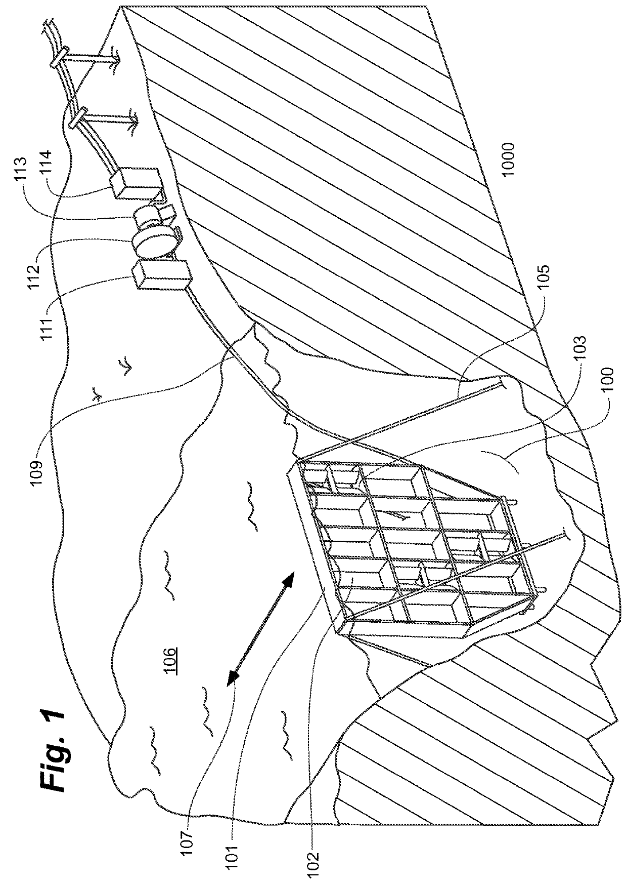
[0033]FIG. 1 illustrates a hydroelectric power system 1000. System 1000 includes a modular water energy conversion system 100 adapted to be placed in a body of water 106 that flows in either or both directions 107 through system 100. In this example, body of water 106 is a river channel. However, the described system can be adapted for use with other ...


PUM


Abstract

Various embodiments of an apparatus and method for extracting useful work from a fluid stream are disclosed. Some embodiments comprise balanced hydrofoils comprising upper and lower semifoils joined by a member. Some embodiments comprise an array of removable hydrofoil modules wherein each module is adapted to provide an independent power contribution to an overall system, depending on speed of the fluid stream in the vicinity of the module, and each module is further adapted to provide its power contribution at a substantially consistent pressure to an array-wide high pressure fluid circuit. These and other embodiments are further disclosed herein.

Description

CROSS-REFERENCE TO RELATED APPLICATIONS[0001]This application claims the benefit of U.S. Provisional Application Ser. No. 62 / 086,704. The entire disclosure of that application is hereby incorporated herein by reference.TECHNICAL FIELD AND BACKGROUND OF THE INVENTION[0002]Hydro-electric power systems have suffered from many deficiencies. These deficiencies have included inefficient power output and significant disruption to the natural environment. Systems that rely on a row of adjacent hydrofoils that achieve flutter oscillation have shown promise for addressing both deficiencies. These principles and specific systems implementing them are shown, for example, in U.S. Pat. No. 4,347,036 (Arnold), U.S. Pat. No. 6,273,680 (Arnold) and U.S. Pat. No. 8,469,663 (Kerr).SUMMARY[0003]Various challenges have remained to effectively implementing an oscillating hydrofoil system for extracting energy from water.[0004]One challenge is that the foils need to be held parallel to each other and perp...

Claims


Application Information

Patent Timeline
IPC IPC(8): F03B17/06F03D5/06F03D9/17
CPCF03B17/06F03D5/06F03D9/17F05B2240/12F05B2240/124F05B2240/40F05B2250/42F05B2260/406Y02E10/70Y02E10/72Y02E60/16Y02E70/30Y02E10/30Y02E10/20
Inventor KERR, COLIN
Owner RESHYDRO
Features
  • Generate Ideas
  • Intellectual Property
  • Life Sciences
  • Materials
  • Tech Scout
  • Unparalleled Data Quality
  • Higher Quality Content
  • 60% Fewer Hallucinations
Learn More