Toy gun bullet container structure

a container and toy gun technology, applied in the direction of spring guns, compressed gas guns, white arms/cold weapons, etc., to achieve the effect of high degree of imitation of a genuine device, easy and efficient mounting and removal, and convenient and efficient us

Active Publication Date: 2018-06-14
KIEN WELL TOY IND
View PDF7 Cites 1 Cited by
  • Summary
  • Abstract
  • Description
  • Claims
  • Application Information

AI Technical Summary

Benefits of technology

[0010]In use, the retaining section of the magazine is inserted, through sliding, into the mounting opening so that the present invention can be rotatably mounted to the magazine through the elastic mounting piece. The mounting and removal is easy and efficient.
[0011]The magazine with the present invention rotatably mounted thereto is combinable with a toy gun to allow the bullets loaded in one of the bullet compartments that is located at a specific position. When the bullets have all been shot, a user may remove the magazine from the toy gun and rotate the bullet container device to drive the bullet compartments to move, so that one of the bullet compartments containing bullets that have not yet been shot can be moved to the specific position and re-combination with the toy gun can be made for subsequent shooting.
[0012]Further, for supplementary loading of bullets into the bullet compartments, the retaining section of the magazine is moved, through sliding, out of the mounting opening to allow for supplementing and reloading bullets. With the above-described techniques, the problems of being inconvenient of use for the prior art bullet compartments can be overcome to achieve advantages of easy and efficient use and high degree of imitation of a genuine device.

Problems solved by technology

In addition to a complicated operation that the insertion bar must be exactly aligned with the insertion slot for achieving the desired perpendicular insertion of the insertion bar, the insertion bar or the insertion slot may be shielded and hidden by the magazine or the bullet container so as to make the use and operation inconvenient.

Method used


Image

  • Toy gun bullet container structure
  • Toy gun bullet container structure
  • Toy gun bullet container structure

Examples


Embodiment Construction

[0024]The following descriptions are exemplary embodiments only, and are not intended to limit the scope, applicability or configuration of the invention in any way. Rather, the following description provides a convenient illustration for implementing exemplary embodiments of the invention. Various changes to the described embodiments may be made in the function and arrangement of the elements described without departing from the scope of the invention as set forth in the appended claims.

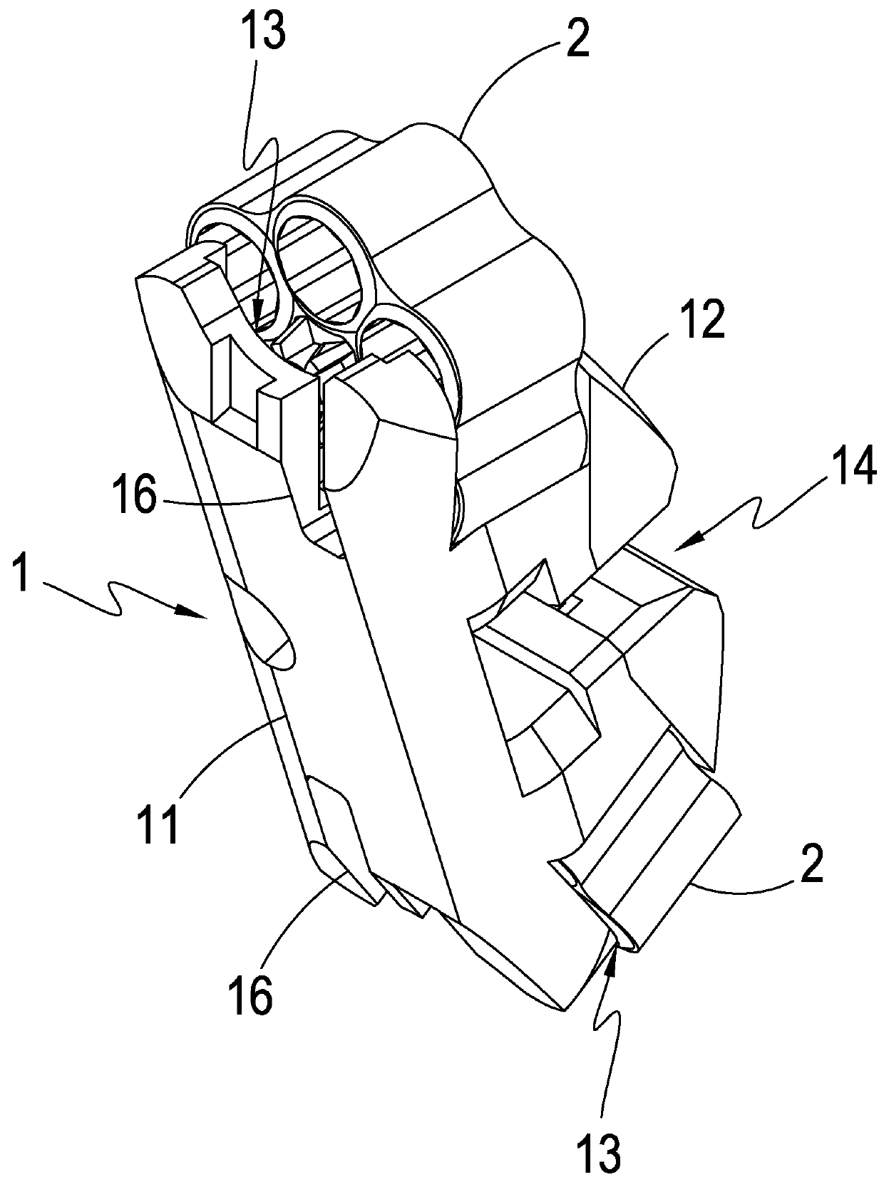
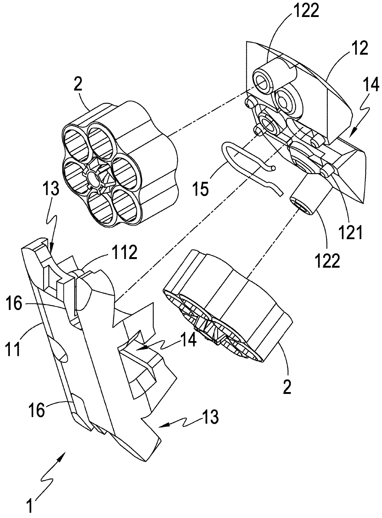
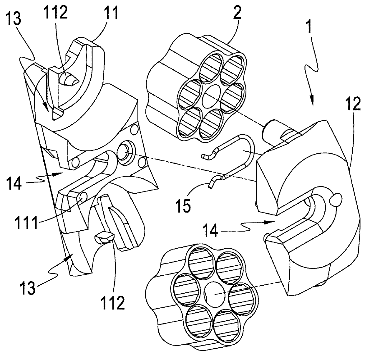
[0025]Referring to FIGS. 1-5, which are respectively a perspective view showing a preferred embodiment of the present invention, an exploded view of the preferred embodiment of the present invention, another exploded view of the preferred embodiment of the present invention, a perspective view illustrating an application of the preferred embodiment of the present invention, and an exploded view of the application of the preferred embodiment of the present invention, it is clearly shown in the drawin...


PUM


Abstract

An improved toy gun bullet container structure includes a bullet container device, which is selectively and movable mounted in a magazine, a receiving space, which is defined in the bullet container device, and a plurality of bullet compartments, which are arranged in the receiving space in a manner of being free to rotate. The bullet compartments each receive and hold therein a plurality of bullets. The magazine is can be mounted and removed so as to achieve imitation of a genuine device. When one of the bullet compartments runs out of bullets, the magazine can be first removed and the bullet container device rotated to switch the other one of the bullet compartments to the position for shooting. When all the bullet compartments run of bullets, the bullet container device can be detached from the magazine for reloading of bullets.

Description

(a) TECHNICAL FIELD OF THE INVENTION[0001]The present invention relates generally to a toy gun bullet container, and more particularly to an improved toy gun bullet container that shows the characteristics of easy and efficient use and high degree of genuineness imitation.(b) DESCRIPTION OF THE PRIOR ART[0002]The vivid development of tog guns and increasingly improved technology of the related fields bring up various sorts of new ideas.[0003]One of these newly emerging ideas is an improvement concerning bullet loading, which involves a magazine and a known bullet container. The magazine is provided, at one side thereof, with an insertion bar. The magazine comprises an insertion slot that is formed in a middle of a sidewall of the magazine for receiving the insertion of the insertion bar and a plurality of bullet storage spaces circumferentially arranged around the insertion bar for receiving and holding therein bullets. In this way, the bullets may be individually held and retained ...

Claims


Application Information

Patent Timeline
Patent Type & Authority Applications(United States)
IPC IPC(8): F41B7/00F41B7/08
CPCF41B7/006F41B11/54F41B7/08F41B7/003F41A9/68
Inventor HUANG, SHUN-CHI
Owner KIEN WELL TOY IND
Why Eureka
Try Eureka