Toroidal sensor

a sensor and thoracic technology, applied in the field of sensors, can solve the problems of conductor breakage, difficult or circuitous routing, and need careful shielding

Active Publication Date: 2018-06-14
TACTUAL LABS
View PDF0 Cites 23 Cited by
  • Summary
  • Abstract
  • Description
  • Claims
  • Application Information

AI Technical Summary

Benefits of technology

[0017]It is also a further object of this disclosure to provide a touch sensor for a stee

Problems solved by technology

In view of the modern trend to reduce bezel size, attaching the rows and columns to the drive and sense circuits may require careful shielding and/or difficult or circuitous routing.
For flat surfaces, this works well, howe

Method used


Image

  • Toroidal sensor
  • Toroidal sensor
  • Toroidal sensor

Examples


Embodiment Construction

[0042]The present application contemplates various embodiments of touch sensors designed for human-computer or human-machine interaction applications. The present application also contemplates various configurations and orientations of touch sensor conductors to sense human-computer or human-machine interaction when combined with touch sensing apparatus. While the touch sensor conductor configurations are suited to use with frequency-orthogonal signaling techniques (see, e.g., U.S. Pat. Nos. 9,019,224 and 9,529,476, and U.S. patent application Ser. No. 14 / 216,791), it may be used with other signal techniques including scanning or time division techniques, and / or code division techniques. It is pertinent to note that the sensors described and illustrated herein are also suitable for use in connection with signal infusion (a / k / a signal injection) techniques and apparatus.

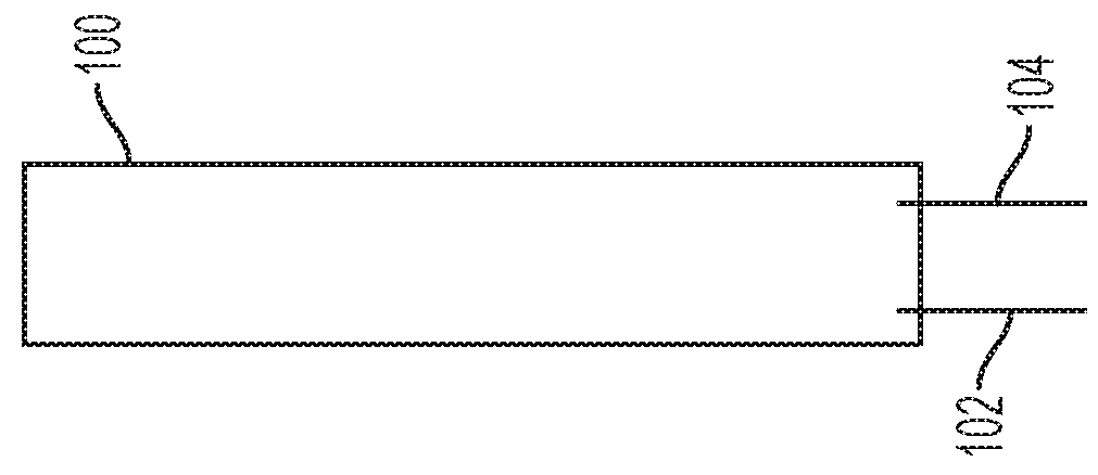
[0043]FIG. 1 shows a high-level illustration of an embodiment of a slide sensor 100 made in accordance with the pre...


PUM


Abstract

A plurality of sensors for application to a steering wheel or other generally toroidal objects is disclosed. In an embodiment, the sensor comprises interleaving transmit and receive conductors. In an embodiment, the sensor comprises crossing transmit and receive conductors. In an embodiment, sensor conductors are first provided on a flat substrate, which sensors placed on the flat substrate in a configuration that will permit expansion application of the substrate to the steering wheel.

Description

[0001]This application is a continuation-in-part of and claims priority to U.S. patent application Ser. No. 15 / 690,242 entitled SINGLE SIDED CAPACITIVE SENSOR, filed on Aug. 29, 2017, and Ser. No. 15 / 692,234 entitled CAPACITIVE SENSOR, also filed on Aug. 29, 2017, and each of those claiming priority to U.S. Patent Application No. 62 / 381,314 which was filed on Aug. 30, 2016.[0002]This application is also a continuation-in-part of and claims priority to U.S. Provisional Patent Application No. 62 / 428,862, filed Dec. 1, 2016 and entitled SIGNAL INJECTION TO ENHANCE APPENDAGE DETECTION AND CHARACTERIZATION.[0003]This application is also claims priority to U.S. Provisional Patent Application No. 62 / 488,753, filed Apr. 22, 2017 and entitled HETEROGENEOUS SENSING APPARATUS AND METHODS, and U.S. Provisional Patent Application No. 62 / 588,267, filed Nov. 17, 2017 and entitled SENSING CONTROLLER, each of which are incorporated herein by this reference as if they had been set forth fully herein....

Claims


Application Information

Patent Timeline
IPC IPC(8): G06F3/044G06F3/01G06F3/0488A63F13/214A63F13/2145A63F13/428
CPCG06F3/044G06F3/014G06F3/04883A63F13/214A63F13/2145A63F13/428A63F13/212A63F13/245A63F13/803G06F1/163G06F3/017G06F2203/04102G06F3/04164G06F3/04166G06F3/0443G06F3/0445G06F3/0448
Inventor LEIGH, DARRENMOSELEY, BRAONALACK, JR., ROBERTFORLINES, CLIFTONLANDA, ADAM
Owner TACTUAL LABS
Why Eureka
Try Eureka