Highly efficient waveguide pulsed THz electromagnetic radiation source and group-matched waveguide THz electromagnetic radiation source

a thz electromagnetic radiation source, high-efficiency technology, applied in the direction of instruments, cladded optical fibres, optical elements, etc., can solve the problems of inconvenient operation, inconvenient maintenance, and inability to meet the needs of users, and achieve the effect of reducing the number of fels

Inactive Publication Date: 2007-09-18
HRL LAB
View PDF5 Cites 44 Cited by
  • Summary
  • Abstract
  • Description
  • Claims
  • Application Information

AI Technical Summary

Problems solved by technology

FELs require enormous resources, space and a dedicated staff to run the facilities.
The cost, weight and size of a FEL are prohibitive.
Operation of such a source requires a strong magnetic field and a very high voltage power supply, making it cumbersome and inefficient.
The second category, namely, electronic techniques of generating THz radiation are very attractive because of their promise of device integration and miniaturization; however, the speed limitations of the current microelectronics prohibit a practical transistor circuit from oscillating in the desired frequency range, i.e., above 0.557 THz.
Though reported output powers are improving continuously, they are still quite low, ca.
Though the output powers of THz gas lasers reach 100 mW, they are very bulky and power-inefficient.
However, the operation of QCLs requires cryogenic equipment to keep

Method used


Image

  • Highly efficient waveguide pulsed THz electromagnetic radiation source and group-matched waveguide THz electromagnetic radiation source
  • Highly efficient waveguide pulsed THz electromagnetic radiation source and group-matched waveguide THz electromagnetic radiation source
  • Highly efficient waveguide pulsed THz electromagnetic radiation source and group-matched waveguide THz electromagnetic radiation source

Examples


first embodiment

[0019]In a first embodiment disclosed herein, a THz electromagnetic radiation source has phase matching.

[0020]In another embodiment disclosed herein, a THz electromagnetic radiation source has phase and group velocity matching.

[0021]The use of optical rectification to generate Terahertz radiation in certain nonlinear materials is a well-know and relatively well-understood phenomenon in the prior art. The mechanism, often referred to as optical rectification, can be explained as follows. An optical field induces a nonlinear polarization P, in the material that is proportional to the local intensity of the optical field. If the envelope of the field is a pulse, moving in a particular direction, then the induced polarization is also a pulse, having the shape and velocity of the optical intensity pulse. In a medium in which the group velocity of the optical and Terahertz waves are the same, the forward-motion of this dipole “grows” a field that has the shape of the derivative of the opt...

second embodiment

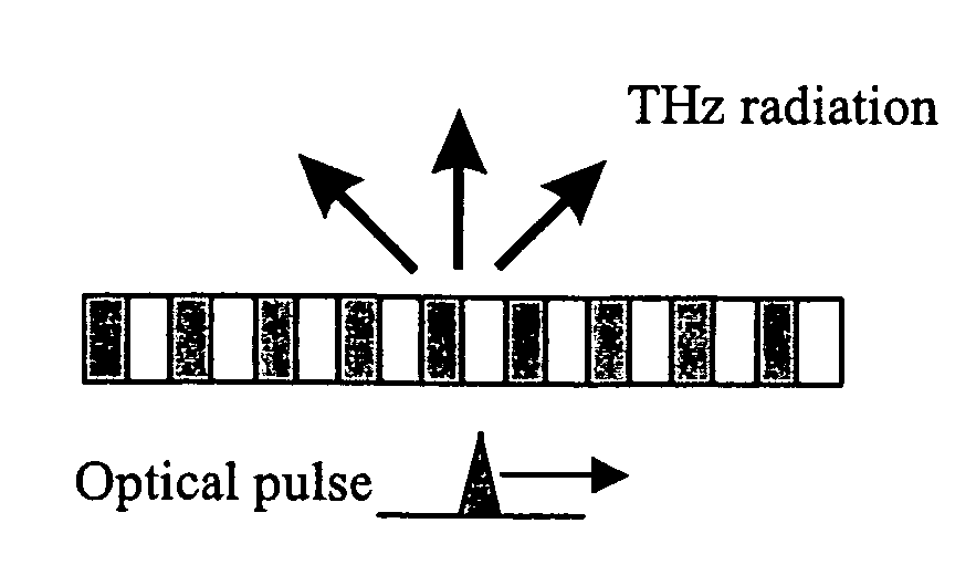
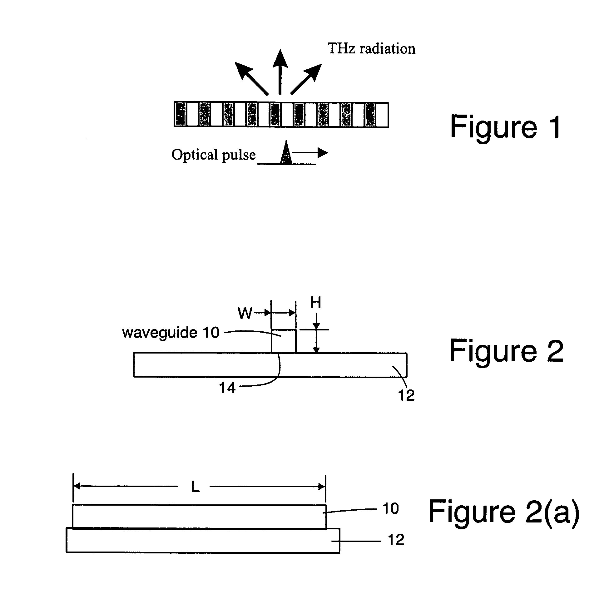
[0025]There are several ways to do this for the moving dipole approach disclosed herein. One is to artificially vary the properties of the material so that one achieves a phase velocity match (see the second embodiment discussed below). This can be done in LiNbO3 by periodically inverting the Ferroelectric domains, a process known as poling. Poling forms regions in which the sign of the nonlinear coefficient can be set to be either positive or negative. When an optical pulse moves through material that has been periodically poled, it forms a local dipole moment that flips direction as it moves from one domain to the next. Thus, to an external observer, the dipole appears to be oscillating as it moves forward. See FIG. 1. The radiation field is that of an oscillating dipole, moving forward with a velocity c / ne, where ne is the optical index of refraction of the material. Because of Doppler shifts, the observed radiation frequency depends upon the direction of radiation. However, for ...


PUM


Abstract

Electromagnetic radiation sources operating in the Terahertz (THz) region capable of overcoming the Manley-Rowe limits of known optical schemes by achieving phase matching between a THz wave and optical pulse in a nonlinear waveguide, or by achieving both phase and group velocity matching between a THz wave and optical pulse in a nonlinear waveguide to yield even higher efficiencies in converting optical power to the THz region.

Description

CROSS REFERENCE TO A RELATED APPLICATION[0001]This application is related to and claims the benefit of U.S. Provisional Application No. 60 / 653,568 filed 15 Feb. 2005, the disclosure of which is hereby incorporated herein by reference.TECHNICAL FIELD[0002]This disclosure relates to electromagnetic radiation sources operating in the Terahertz (THz) region. In particular, the present disclosure relates to a design for a highly efficient THz source based on nonlinear optical pulse rectification in a waveguide that is capable of overcoming the Manley-Rowe limits of other optical schemes by achieving phase matching between a THz wave and optical pulse in a nonlinear waveguide. The present disclosure is further related to a scheme that achieves both phase and group velocity matching between a THz wave and optical pulse in a nonlinear waveguide to yield even higher efficiencies in converting optical power to the THz region.BACKGROUND OF THE DISCLOSURE[0003]The methods of generating electrom...

Claims


Application Information

Patent Timeline
IPC IPC(8): H01S3/10G02B6/02
CPCG02F1/365G02F1/3544G02F2203/13
Inventor HAYES, ROBERT R.IONOVA, LEGAL REPRESENTATIVE, IRINA V.IONOV, DECEASED, STANISLAV
Owner HRL LAB
Why Eureka
Try Eureka