Optical zoom with movable pupil

Active Publication Date: 2018-06-21
THALES SA
View PDF4 Cites 3 Cited by
  • Summary
  • Abstract
  • Description
  • Claims
  • Application Information

AI Technical Summary

Benefits of technology

The patent text explains that the position of the pupil in a camera is important for minimizing aberrations and distortions. When zooming in or out, the position of the pupil is adjusted to reduce coma and astigmatism for longer focal lengths, or field curvature for short focal lengths. This results in higher quality photos taken at different zoom distances.

Problems solved by technology

Zooms of this type work over a wide range of focal lengths referred to as their “range” and often possess front optics of large diameter that are both tricky to produce, expensive and may increase the weight of and unbalance the zoom.
The following compromises may in particular be made: the “range” of the zoom may be decreased, focal lengths increased, aperture decreased, the aperture allowed to vary as a function of the position of the zoom in its range or “to ramp” but these compromises are necessary to the detriment of final performance.
Nevertheless, such a method turns out to be effective above all for zooms having a low range and quickly becomes ineffective for high ranges.
Moreover, this solution is rarely envisaged for reasons of aesthetics and because of problems with seal tightness that this may sometimes occasion, the zoom not working at constant volume.
Such a system is also effective only for zooms having reasonable zoom ranges, because although it allows the diameter of the front optics to be decreased, it leads to a significant increase in the diameters of the lenses of the second and third elements.
The second obstacle limiting the rays after the pupil is the stop.
Another of the drawbacks of the latter type of solutions is that the movement of the pupil leads to changes in the aperture of the zoom, which are undesirable.

Method used


Image

  • Optical zoom with movable pupil
  • Optical zoom with movable pupil
  • Optical zoom with movable pupil

Examples


Embodiment Construction

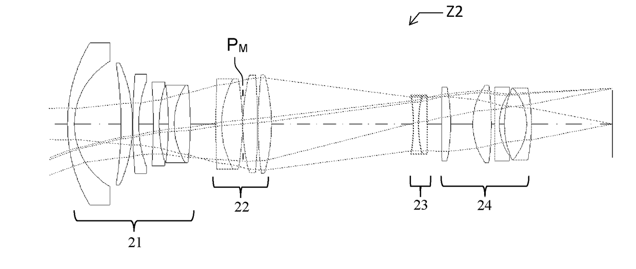
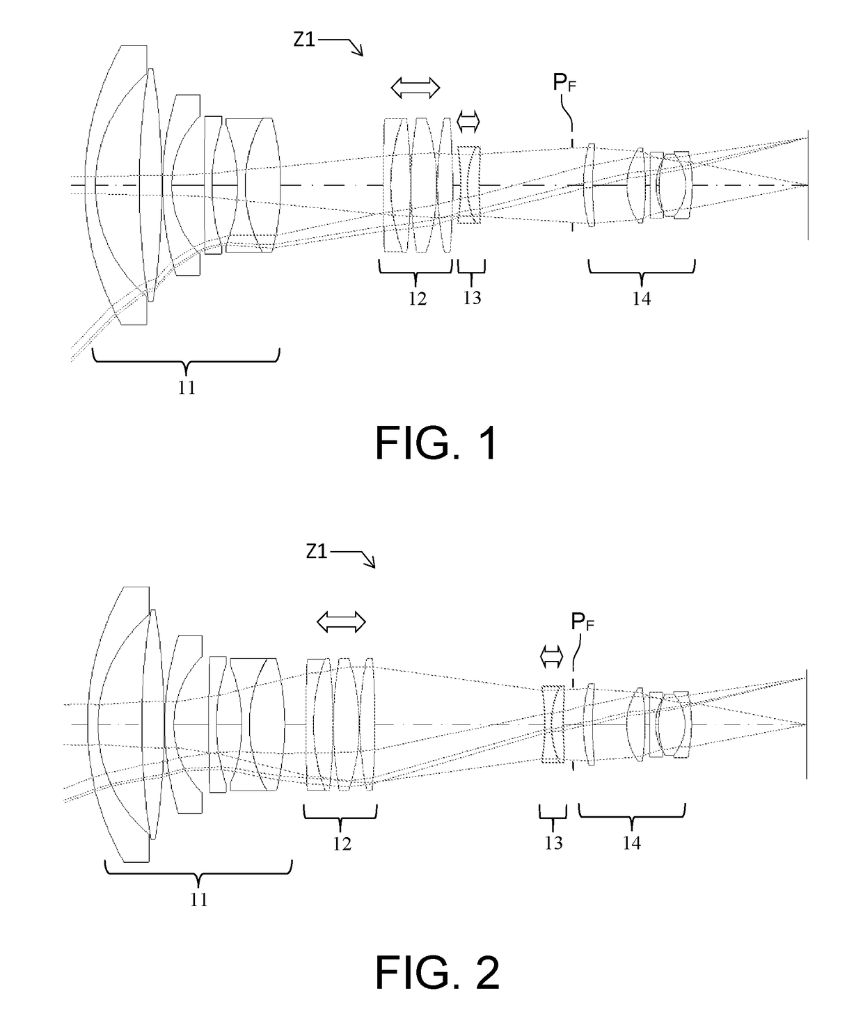
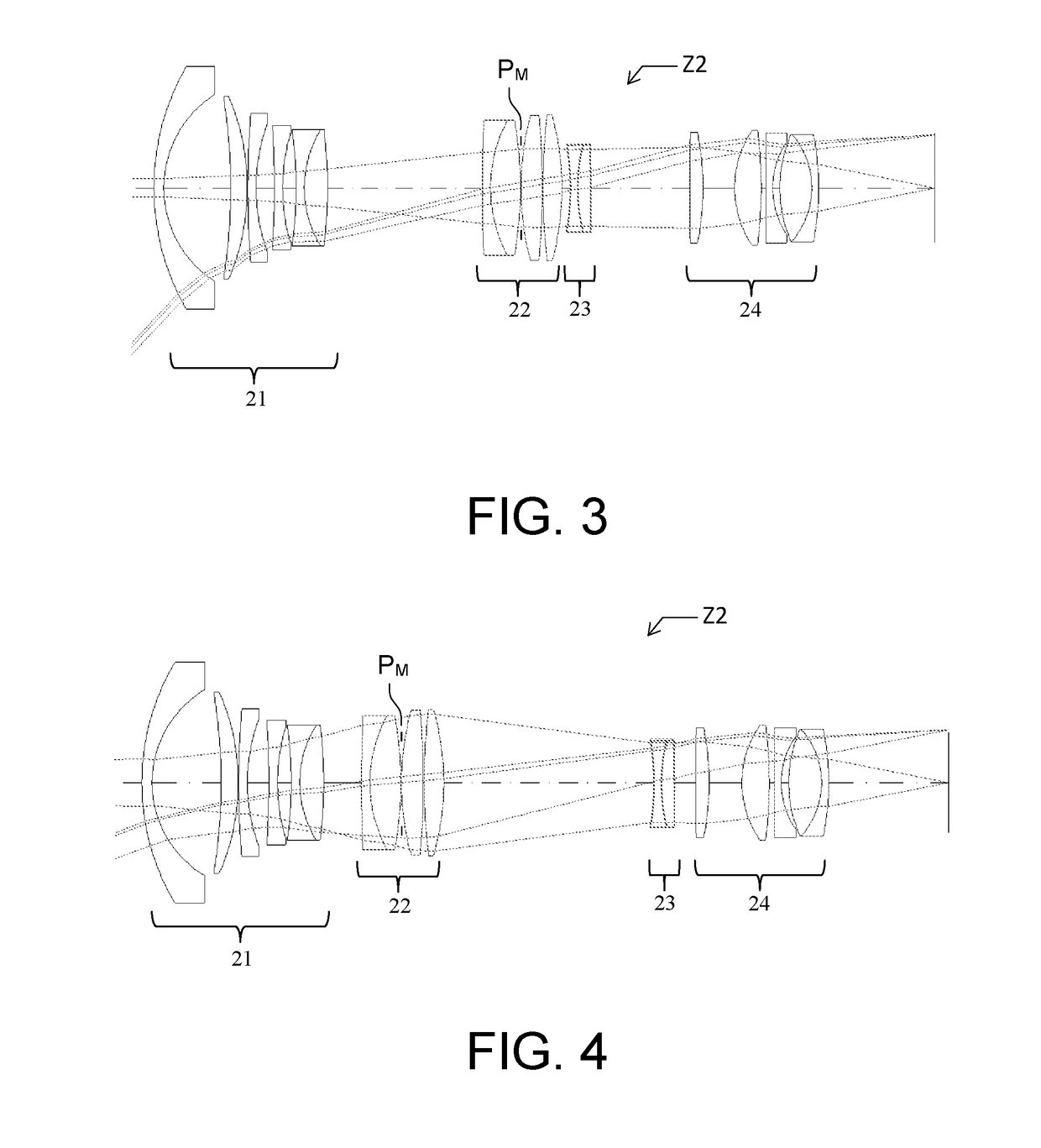
[0038]The zoom according to the invention possesses four groups of lenses, which groups are called “elements” and are successively numbered from 1 to 4, the element 1 being located at the entrance of the zoom and the element 4 at the exit closest to the focal plane. The element 1 of said zoom is fixed and its position depends on focal length; the elements 2 and 3 are movable. These elements 2 and 3 are convergent and divergent, respectively. They allow the focal length of the zoom to be varied while preserving a fixed image plane. The element 4 is a fixed convergent element.

[0039]The zoom includes a movable pupil that is embodied by an iris the diameter of the aperture of which may be made to vary via a mechanical action. This iris may be located in the element 2 of the zoom, between its element 2 and its element 3, in its element 3 or between its element 3 and its element 4. The diameter of this iris is adjusted depending on the position that it occupies in the system. It is thus p...


PUM


Abstract

An optical zoom including a movable pupil that moves according to a movement law, comprises four successive groups of lenses, the first group and the fourth group being fixed, the second group and the third group being movable and placed between the first and fourth groups, the second group being a convergent group and the third group being a divergent group. In a first variant, the diameter of the movable pupil varies according to a variation law, depending on the movement law of the movable pupil. In a second variant, the optical zoom includes a movable stop, the movable stop moving according to a second movement law, the diameter of this stop varying according to a second variation law, depending on the second movement law of the movable stop.

Description

CROSS-REFERENCE TO RELATED APPLICATIONS[0001]This application claims priority to foreign French patent application No. FR 1601807, filed on Dec. 20, 2016, the disclosure of which is incorporated by reference in its entirety.FIELD OF THE INVENTION[0002]The field of the invention is that of imaging objectives, and more precisely, that of optical zooms. By optical zoom what is meant is an optic in which the field variation is achieved optically and not electronically.BACKGROUND[0003]A zoom generally possesses a plurality of optical subassemblies called “elements”, certain of which are fixed and others of which are movable along the optical axis of the system. A conventional zoom architecture comprises a plurality of optical elements:[0004]a fixed first element that allows an image, which is most often virtual, of the observed object to be formed, which image is received by a second element;[0005]movable second and third elements that allow the focal length of the zoom to be varied and ...

Claims


Application Information

Patent Timeline
IPC IPC(8): G02B15/14G02B27/00
CPCG02B15/14G02B27/0025G02B15/177G02B27/0012G02B15/144511
Inventor COUMERT, BRUNOMANEVAL, FLORENCE
Owner THALES SA
Why Eureka
Try Eureka