Optical imaging lens

An optical imaging lens and imaging surface technology, applied in optics, optical components, instruments, etc., can solve the problem of unclear shooting of the details of the optical imaging lens.

Active Publication Date: 2021-07-16
ZHEJIANG SUNNY OPTICAL CO LTD
View PDF7 Cites 0 Cited by
  • Summary
  • Abstract
  • Description
  • Claims
  • Application Information

AI Technical Summary

Problems solved by technology

[0004] The main purpose of the present invention is to provide an optical imaging lens to solve the problem that the detailed image of the optical imaging lens in the prior art is unclear

Method used


Image

  • Optical imaging lens
  • Optical imaging lens
  • Optical imaging lens

Examples


Embodiment 1

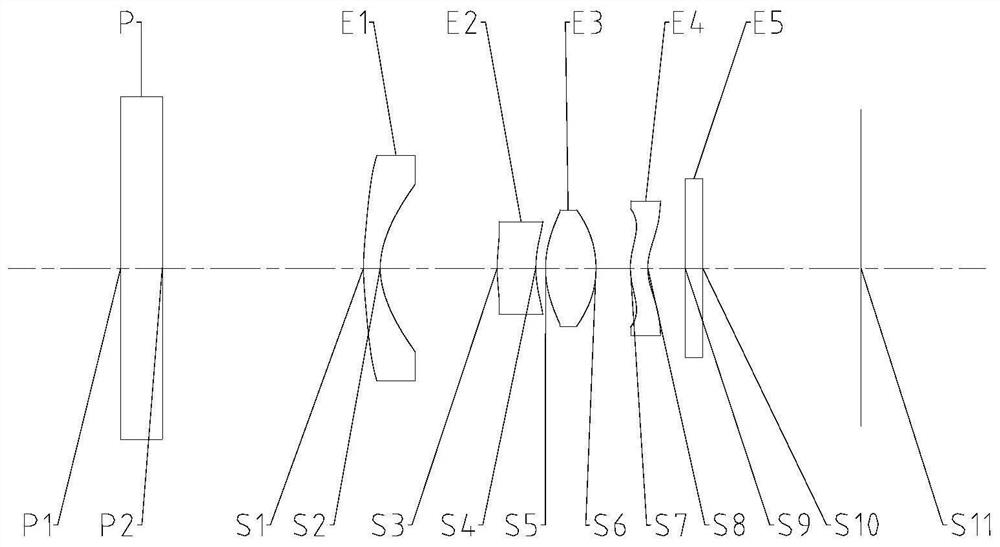
[0059] Such as Figure 1 to Figure 30 As shown, along the optical axis, from the object side of the optical imaging lens to the image side of the optical imaging lens, the plane glass, the first lens, the second lens, the third lens and the fourth lens are sequentially included; the image side of the first lens is a concave surface; The fourth lens has a negative refractive power; wherein, half the Semi-FOV of the maximum field of view of the optical imaging lens satisfies: Semi-FOV>40°; the effective focal length f1 of the first lens and the combination of the second lens and the third lens The focal length between f23 satisfies: -1.0

[0060] By arranging plane glass on the object side of the first lens, the plane glass can protect the rear lens, and at the same time, the image side of the first lens is set as a concave surface, and the fourth lens is set as a negative refractive power, which can maintain light Under the premise of good convergence, the optical...

Embodiment 2

[0078] Such as Figure 1 to Figure 30 As shown, along the optical axis, from the object side of the optical imaging lens to the image side of the optical imaging lens, plane glass is sequentially included; a first lens, a second lens; a third lens and a fourth lens, and the image side of the first lens is a concave surface; The fourth lens has a negative refractive power; wherein, half the Semi-FOV of the maximum field of view of the optical imaging lens satisfies: Semi-FOV>40°; the air interval T12 between the first lens and the second lens on the optical axis and the optical When the imaging lens is in the minimum object distance state, the distance BFL1 between the image side of the fourth lens and the imaging surface of the optical imaging lens on the optical axis satisfies: 0

[0079] By arranging plane glass on the object side of the first lens, the plane glass can protect the rear lens, and at the same time, the image side of the first lens is set as a con...


PUM


Abstract

The invention provides an optical imaging lens. The optical imaging lens sequentially comprises: from the object side of the optical imaging lens to the image side of the optical imaging lens along an optical axis,plain glass; a first lens, wherein the image side surface of the first lens is a concave surface; a second lens; a third lens; and a fourth lens with negative focal power. The half Semi-FOV of the maximum field angle of the optical imaging lens meets the condition: Semi-FOV> 40 DEG C; the effective focal length f1 of the first lens and the combined focal length f23 of the second lens and the third lens meet the following formula:-1.0< f23 / f1< -0.5. The optical imaging lens solves the problem that in the prior art, an optical imaging lens cannot shoot detail images clearly.

Description

technical field [0001] The present invention relates to the technical field of optical imaging equipment, in particular to an optical imaging lens. Background technique [0002] With the popularization and use of mobile phones, the application of mobile phones has been developed rapidly, and users have higher and higher requirements for mobile phone cameras, and users' demand for mobile phones is no longer limited to some single shooting functions. When taking pictures, when the lens is very close to the object, clear photos cannot be taken. Therefore, it is not easy to take detailed pictures in the mobile phone camera in the prior art. [0003] That is to say, the optical imaging lens in the prior art has the problem that the detailed images are not clear. Contents of the invention [0004] The main purpose of the present invention is to provide an optical imaging lens to solve the problem that the detailed image of the optical imaging lens in the prior art is unclear. ...

Claims


Application Information

Patent Timeline
Patent Type & Authority Applications(China)
IPC IPC(8): G02B13/00G02B13/06G02B13/18
CPCG02B13/004G02B13/0055G02B13/06G02B13/18
Inventor 崔甲臣黄林戴付建赵烈烽
Owner ZHEJIANG SUNNY OPTICAL CO LTD
Why Eureka
Try Eureka