
Multi-Channel Optical System

a multi-channel optical system and optical design technology, applied in the field of multi-channel optical systems, can solve the problems of long system length, difficult beam cube material, complicated optical design, etc., and achieve the effect of high optical performan

Active Publication Date: 2020-08-13
CHARLES STARK DRAPER LABORATORY
View PDF15 Cites 0 Cited by
  • Summary
  • Abstract
  • Description
  • Claims
  • Application Information

AI Technical Summary

Benefits of technology

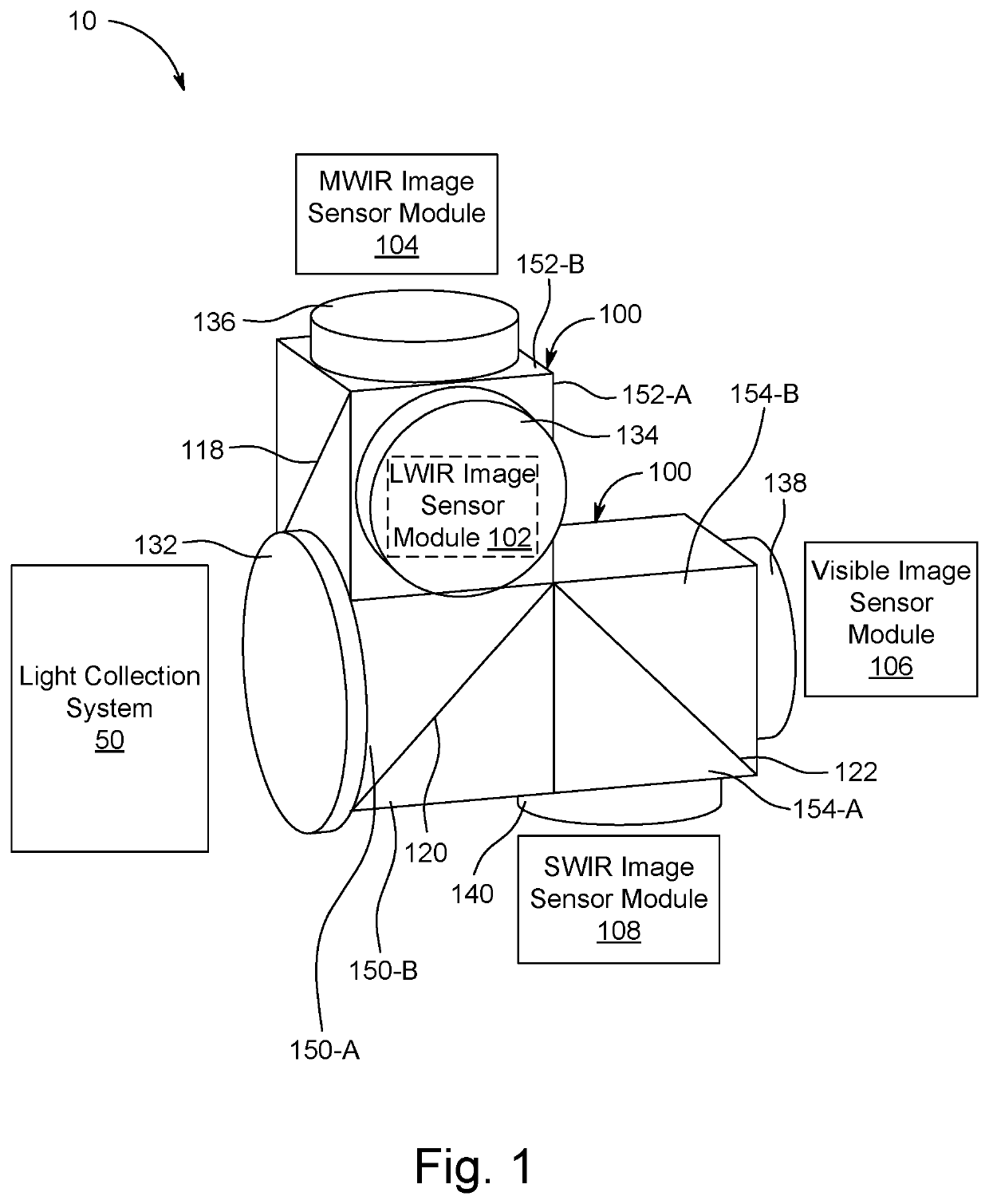
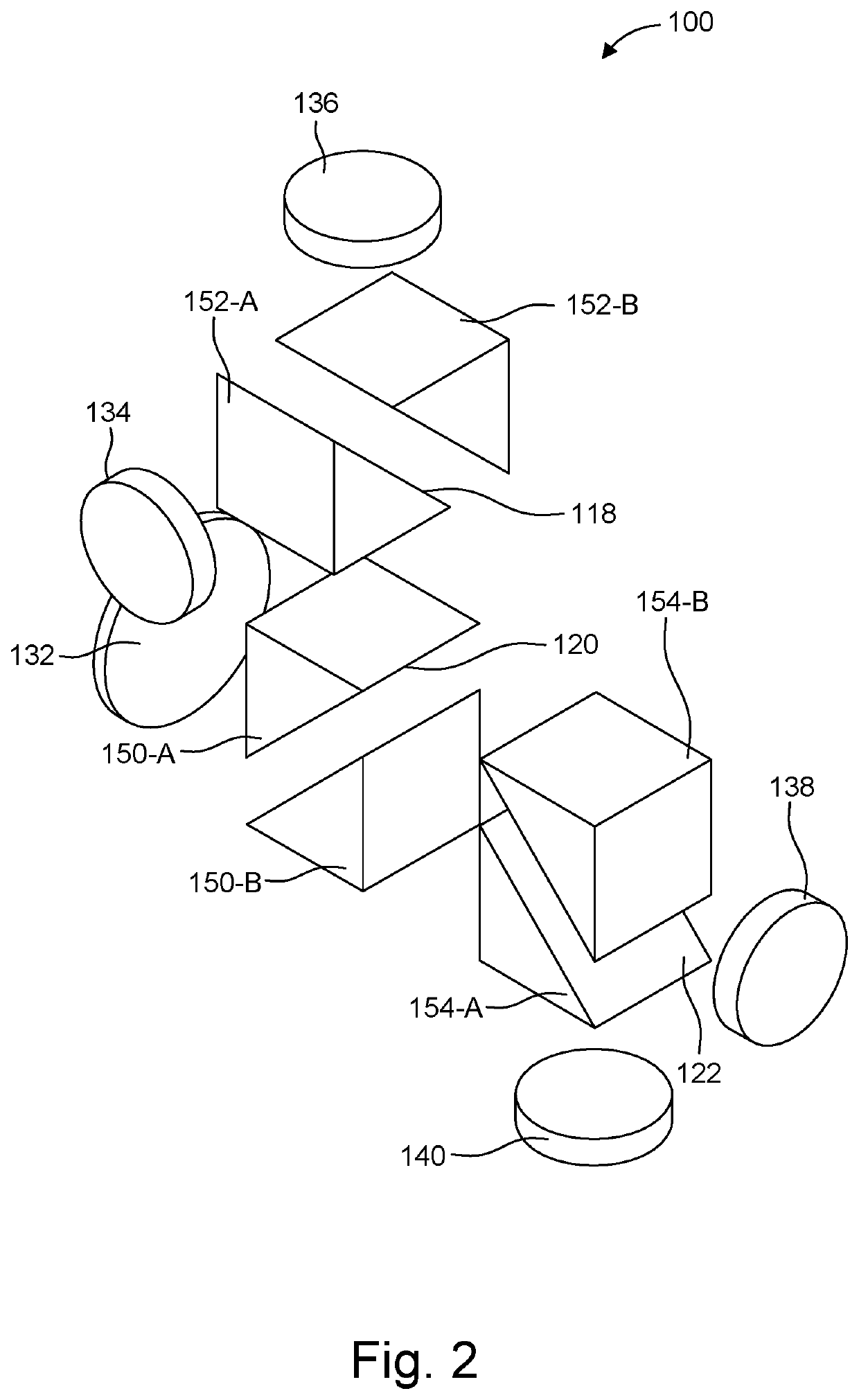
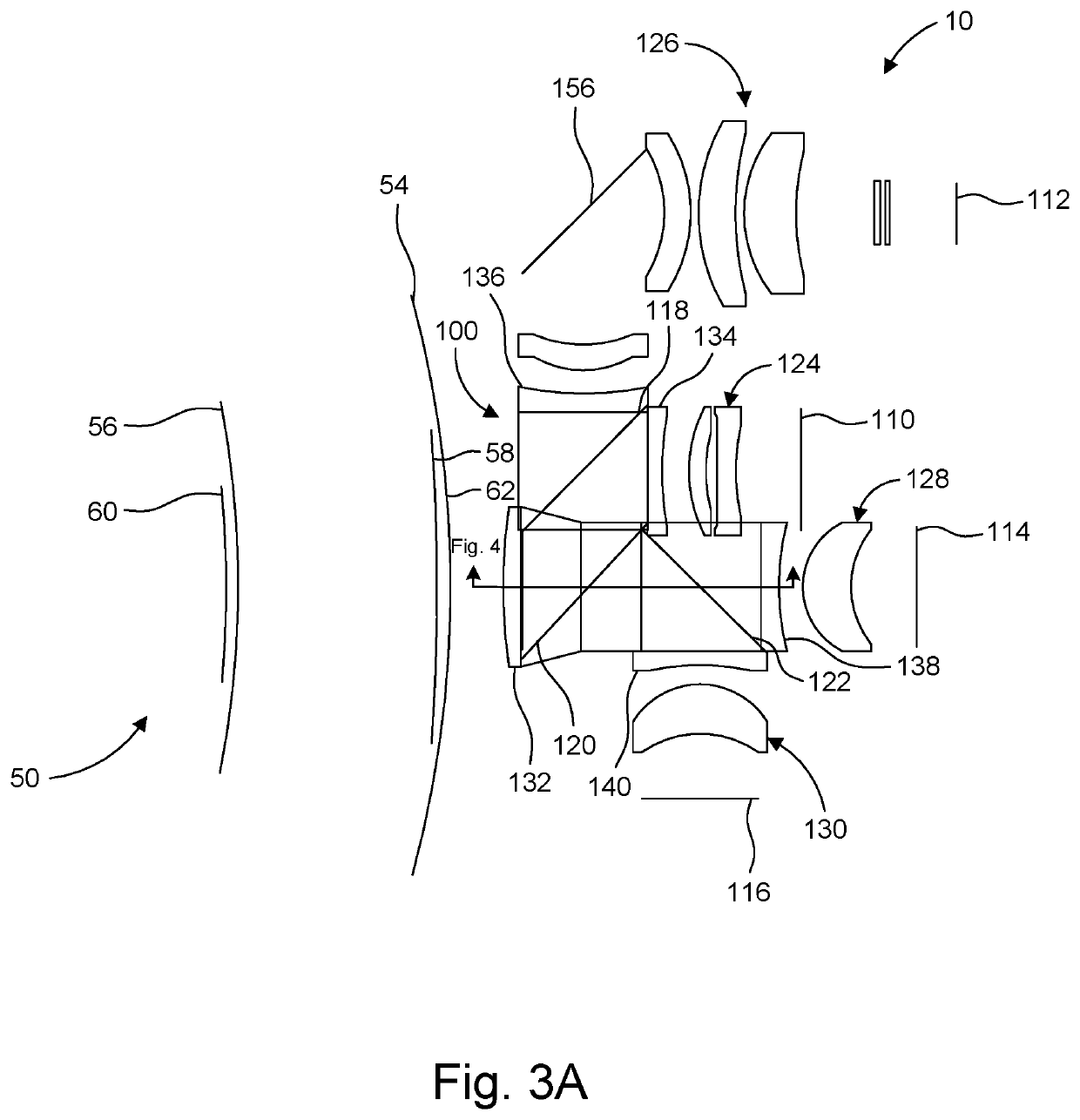
The present invention is about a system that can split off one band of light from another using a special plate called a parallel plane plate (PPP). However, this method causes significant non-symmetrical aberrations that can be corrected by adding collimation or a second PPP. The invention solves this problem by using wavefront compensators that match the curvature of the wavefronts of the incoming and exiting light. This results in a high-performing multi-channel beamsplitter system that is not affected by the material dispersion of the incoming light.

Problems solved by technology

Both of these solutions, however, complicate the optical design and also tend to lengthen the system.
Moreover, especially in a multiband system, the beam cube material is a challenge because of the required wide spectral band.

Method used


Image

  • Multi-Channel Optical System
  • Multi-Channel Optical System
  • Multi-Channel Optical System

Examples


Embodiment Construction

[0024]The invention now will be described more fully hereinafter with reference to the accompanying drawings, in which illustrative embodiments of the invention are shown. This invention may, however, be embodied in many different forms and should not be construed as limited to the embodiments set forth herein; rather, these embodiments are provided so that this disclosure will be thorough and complete, and will fully convey the scope of the invention to those skilled in the art.

[0025]As used herein, the term “and / or” includes any and all combinations of one or more of the associated listed items. Further, the singular forms and the articles “a”, “an” and “the” are intended to include the plural forms as well, unless expressly stated otherwise. It will be further understood that the terms: includes, comprises, including and / or comprising, when used in this specification, specify the presence of stated features, integers, steps, operations, elements, and / or components, but do not pre...


PUM


Abstract

A multi channel beamsplitter system operating over a wide spectral band has high optical performance despite the fact that the incoming and / or exiting light is not collimated and its material is dispersive. This is achieved using wavefront compensators that are matched to the curvature of the wavefronts of the incoming and / or exiting light.

Description

RELATED APPLICATIONS[0001]This application claims the benefit under 35 USC 119(e) of U.S. Provisional Application No. 62 / 803,025, filed on Feb. 8, 2019, which is incorporated herein by reference in its entirety.BACKGROUND OF THE INVENTION[0002]Digital camera systems will operate in the wavelengths in which their image sensors can detect light. Common consumer camera systems detect light in the visible wavelength band and their sensitivity may extend into the near infrared (IR) band. In such systems, standard glass refractive lenses are often used. That said, other image sensors work in longer wavelength bands. For example, InGaAs image sensors cover the short wave IR (SWIR) band, HgCdTe (MCT) image sensors cover the medium wave IR (MWIR) band, and Vanadium Oxide (VOx) image sensors operate into the long wave IR (LWIR) band. And, different lens materials will typically be used in these other bands.[0003]There are a number of established and emerging areas of technology that require m...

Claims


Application Information

Patent Timeline
IPC IPC(8): G02B27/00G02B17/06G02B27/10G02B27/14
CPCG02B27/1006G02B17/0652G02B27/0037G02B27/149G02B17/084G02B27/1013G02B13/008
Inventor SINCLAIR, MATTHEW A.KELSEY, ADAM F.LANDIS, DAVID A.GOLMON, STEPHANIE L.CLEMMER, BUDDYLAINE, JUHA-PEKKA
Owner CHARLES STARK DRAPER LABORATORY
Learn More