
Roof drain cover

Active Publication Date: 2018-07-12
ROOFGUARD MFG LLC
View PDF5 Cites 4 Cited by
  • Summary
  • Abstract
  • Description
  • Claims
  • Application Information

AI Technical Summary

Benefits of technology

The patent is about a drain cover that can be used with different types of drains, such as roof, floor, and street grating. The cover is easy to install and prevents blockages while still allowing fluid to flow through. It also has an extended outer flow ring that helps with fluid collection. Overall, the drain cover has improved functionality and can be used in different types of drainages.

Problems solved by technology

Because roof drains are typically exposed to the elements, they are susceptible to damage or clogging from a variety of sources.
Also, due to their isolation, any damage or tampering with such drains may go unnoticed until a problem occurs with the functioning of the drain.
Further, harmful elements may damage or clog the drains, such as hail or strong winds and solid debris carried by such elements.
Other drains besides those intended for the roof may also be susceptible to similar problems.
For example, street drains may be susceptible to clogging from collected street debris or to damage by passersby.
Therefore, drains in many contexts may be exposed to danger.
However, typical drain covers have many drawbacks.
This limits the number of types of drains that may be fitted with the covers.
In addition, conventional drain covers easily clog and prevent the passage of fluid, due to leaves or other debris building up along the outside of the covers.
Further, the gravel guard on typical covers severely impede the flow of fluids into the cover as well.

Method used


Image

  • Roof drain cover
  • Roof drain cover
  • Roof drain cover

Examples


Embodiment Construction

[0090]In the following discussion that addresses a number of embodiments and applications, reference is made to the accompanying drawings that form a part hereof, and in which is shown by way of illustration specific embodiments in which the embodiments described herein may be practiced. It is to be understood that other embodiments may be utilized and changes may be made without departing from the scope of the disclosure.

[0091]Various inventive features are described below that can each be used independently of one another or in combination with another feature or features. However, any single inventive feature may not address all of the problems discussed above or only address one of the problems discussed above. Further, one or more of the problems discussed above may not be fully addressed by the features of each embodiment described below.

[0092]In certain embodiments, the cover disclosed herein prevents or reduces the blockage of fluid from entering a drain caused by the buildu...


PUM


Abstract

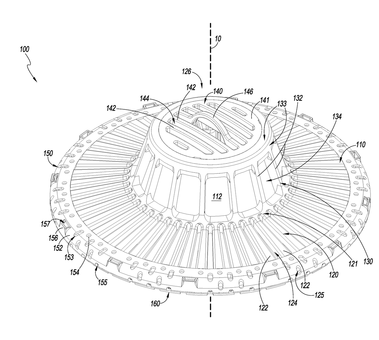
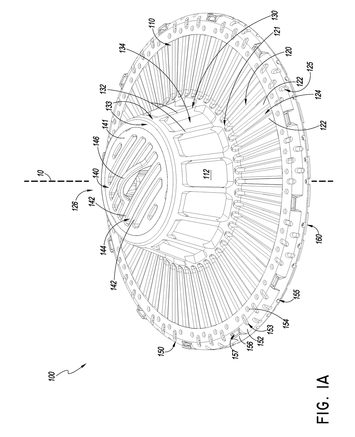
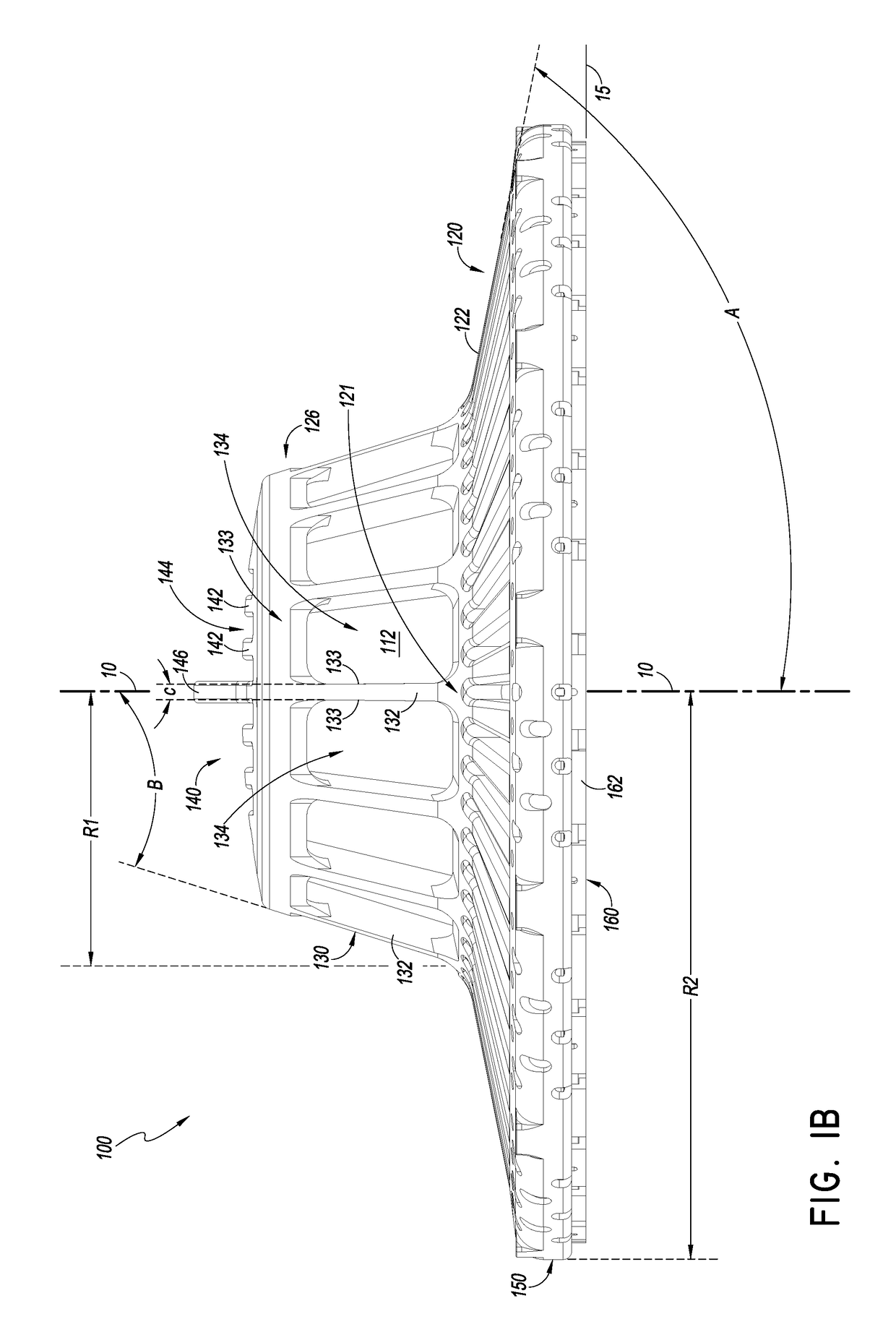
A cover for a drain. The cover may be used with roof drains or other drains and allow for fluid collection into the drain even with buildup of debris around or on the cover. The cover may have a lower flange or skirt portion with a large area and extending outwardly in an arcuate or polygonal configuration and having openings for fluid flow. The lower portion may be oriented at a positive, zero, or negative angle with respect to the horizontal. The lower portion may be wider than a drain body over which the cover is used. An upper portion may be connected to the lower portion and may be more vertically-oriented than the lower portion and having openings.

Description

INCORPORATION BY REFERENCE TO ANY PRIORITY APPLICATIONS[0001]Any and all applications, for which a foreign or domestic priority claim is identified in the Application Data Sheet as filed with the present application, are hereby incorporated by reference under 37 CFR 1.57.[0002]This application is a continuation-in-part of U.S. patent application Ser. No. 15 / 016,880, entitled ROOF DRAIN COVER and filed on Feb. 5, 2016, which claims the benefit of priority under 35 U.S.C. § 119(e) to U.S. provisional patent application No. 62 / 113,255, entitled ROOF DRAIN COVER and filed Feb. 6, 2015, to U.S. provisional patent application No. 62 / 113,701, entitled ROOF DRAIN COVER and filed Feb. 9, 2015, and to U.S. provisional patent application No. 62 / 268,945, entitled ROOF DRAIN COVER and filed Dec. 17, 2015, and this application claims the benefit of U.S. provisional patent application No. 62 / 520,195, entitled ROOF DRAIN COVER and filed Jun. 15, 2017, the entire disclosure of each of which is incor...

Claims


Application Information

Patent Timeline
IPC IPC(8): E04D13/04
CPCE04D13/0409E04D2013/0413E03F5/06
Inventor HUBER, DONALD G.
Owner ROOFGUARD MFG LLC
Learn More