Ventilating fan

a technology of ventilating fan and fan body, which is applied in the field of ventilating fan, can solve the problems of reducing the sensing accuracy of humidity sensors, not accurately or precisely detecting indoor humidity, etc., and achieves the effect of suppressing the influence of water vapor or water droplets, accurately detecting indoor humidity, and preventing the decrease of the detection accuracy of humidity sensors

Active Publication Date: 2018-07-12
PANASONIC CORP +1
View PDF4 Cites 5 Cited by
  • Summary
  • Abstract
  • Description
  • Claims
  • Application Information

AI Technical Summary

Benefits of technology

[0022]1. The air may flow at a high speed in the humidity sensor box, and it is easy for the water vapor to flow out of the humidity sensor box with the flow without being accumulated inside the humidity sensor box, thereby suppressing the influence of the water vapor or the water droplet on the humidity sensor and enabling the humidity sensor to accurately detect the indoor humidity;
[0023]2. since the diameter of the orifice of the air outlet of the humidity sensor box is small enough, surface tension of the water may prevent the water droplet from entering into the humidity sensor box through the orifices, thereby preventing decreasing of the detection accuracy of the humidity sensor;
[0024]3. positions of the first air inlet of the outer box lid and the position of the second air inlet of the inner box lid are offset from each other, thereby effectively preventing the water droplet from entering into the box body; and
[0025]4. the entire assembly process does not require screws and the like, and the box lid and the box body are fitted together by a hinge, and the number of components is small and the assembly is simple, thereby improving the simplicity of the assembly and saving manufacturing time.

Problems solved by technology

In other words, the humidity sensor has a decreased sensing accuracy, and may not accurately or precisely detect the indoor humidity.

Method used


Image

  • Ventilating fan
  • Ventilating fan
  • Ventilating fan

Examples


Embodiment Construction

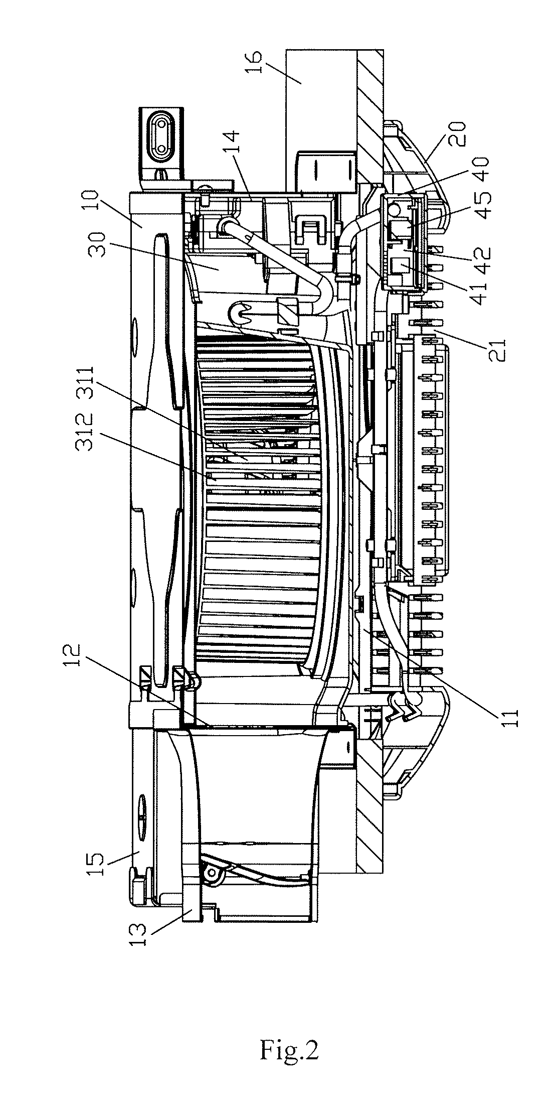
[0043]To make the objectives, technical solutions and advantages of the present disclosure clearer, the present disclosure is further described in detail below in combination with the detailed embodiments with reference to the accompanying drawings.

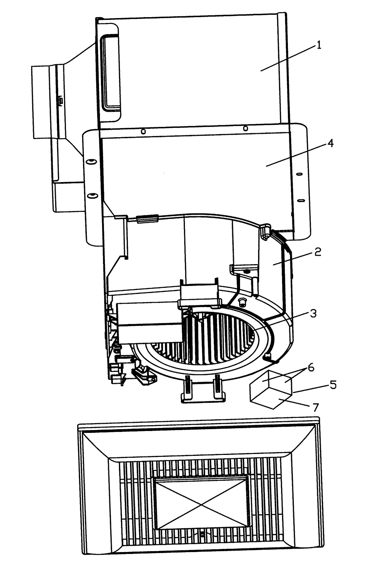
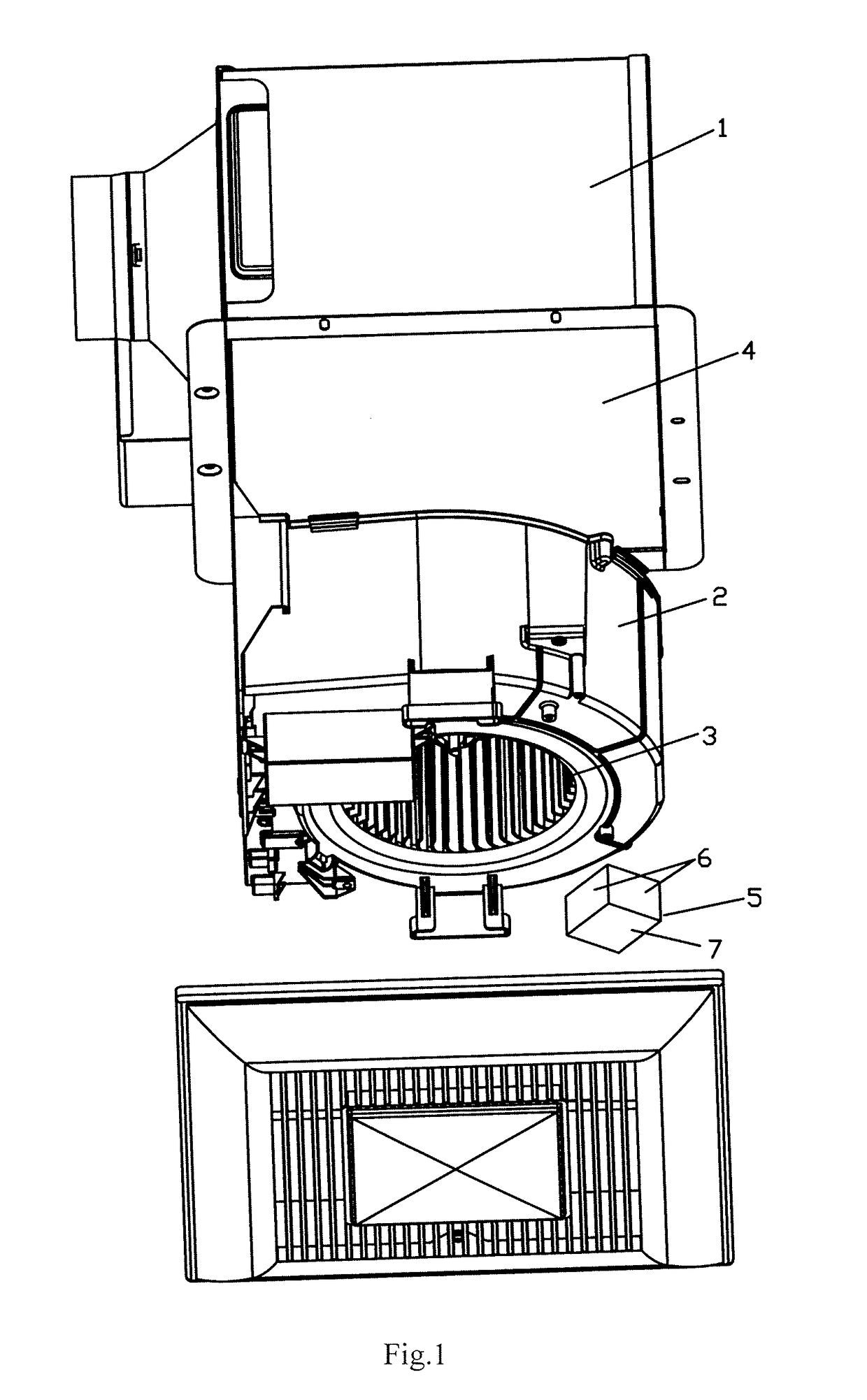
[0044]The ventilating fan according to an embodiment of the present disclosure, as shown in FIG. 2, may be installed in a space between the ceiling 16 and the roof and may also be installed on the wall. In the specification and claims of the present disclosure, the terms “bottom”, “top”, “horizontal”, “longitudinal” and the like are used to indicate the orientations or the positional relationship of various components, on the basis that the ventilating fan is installed in the space between the ceiling 16 and the roof. The terms for indicating the orientations or the positional relationship of the various components are merely for convenience and simplification of description of the present disclosure, rather than indicating or implying th...


PUM


Abstract

A ventilating fan, includes a humidity sensor box, provided with an air inlet in a bottom surface facing an suction opening and an air outlet in a top surface opposite to the bottom surface; a humidity sensor located inside the humidity sensor box and adapted to detect the humidity of the air passing through the humidity sensor box; and a humidity sensor circuit board located inside the humidity sensor box, disposed perpendicular to the bottom surface and adapted to control the humidity sensor. The air may flow at a high speed in the humidity sensor box, and it is easy for the water vapor to be taken out of the humidity sensor box without being accumulated inside the humidity sensor box, thereby suppressing the influence of the water vapor or the water droplet on the humidity sensor and enabling the humidity sensor to accurately detect the indoor humidity.

Description

CROSS REFERENCE TO RELATED APPLICATIONS[0001]This application claims priority to Chinese Application No. 201720048431.4, filed Jan. 12, 2017, the contents of such application being incorporated by reference herein.BACKGROUND OF THE INVENTIONField of the Invention[0002]The present disclosure relates to a ventilating fan, in particular to a ventilating fan with a humidity sensor.[0003]Description of the Related Art[0004]In order to make the ventilating fan run automatically according to the change of ambient environment, the existing ventilating fan is generally equipped with a body sensor, a humidity sensor, a carbon monoxide sensor and the like, and real-time detection to the ambient environment is performed by the various sensors, and the ventilating fan is controlled to turn on / off or change operation speed, according to the detecting result, such as a ventilating fan with a humidity sensor as described in China utility model patent ZL201320384615.X.[0005]FIG. 1 is a schematic str...

Claims


Application Information

Patent Timeline
Patent Type & Authority Applications(United States)
IPC IPC(8): F24F11/00F24F11/74
CPCF24F11/0008F24F11/0001F24F11/74F24F2110/20F24F7/025F24F7/013F24F13/222
Inventor WU, QIMINGNONOSHITA, SHUTO
Owner PANASONIC CORP
Why Eureka
Try Eureka