
Surface fastener, cushioning structure, and seat structure

Active Publication Date: 2018-07-19
DELTA TOOLING CO LTD +1
View PDF0 Cites 0 Cited by
  • Summary
  • Abstract
  • Description
  • Claims
  • Application Information

AI Technical Summary

Benefits of technology

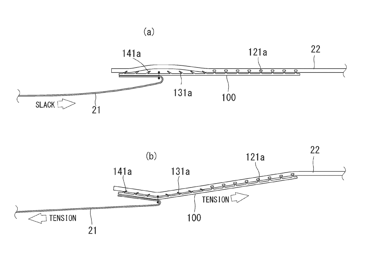
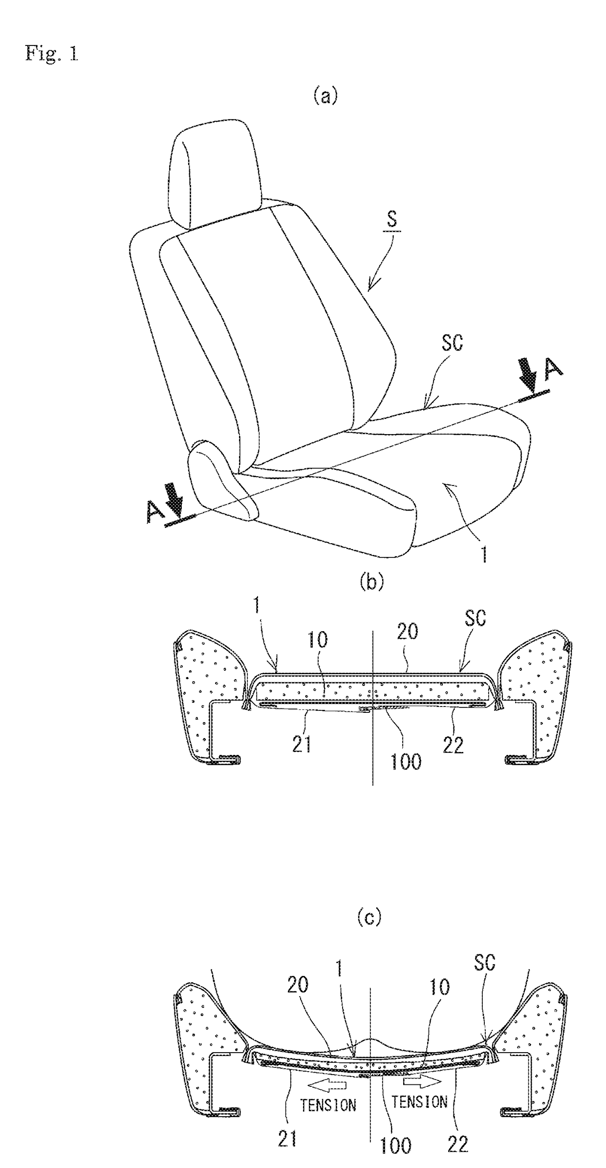
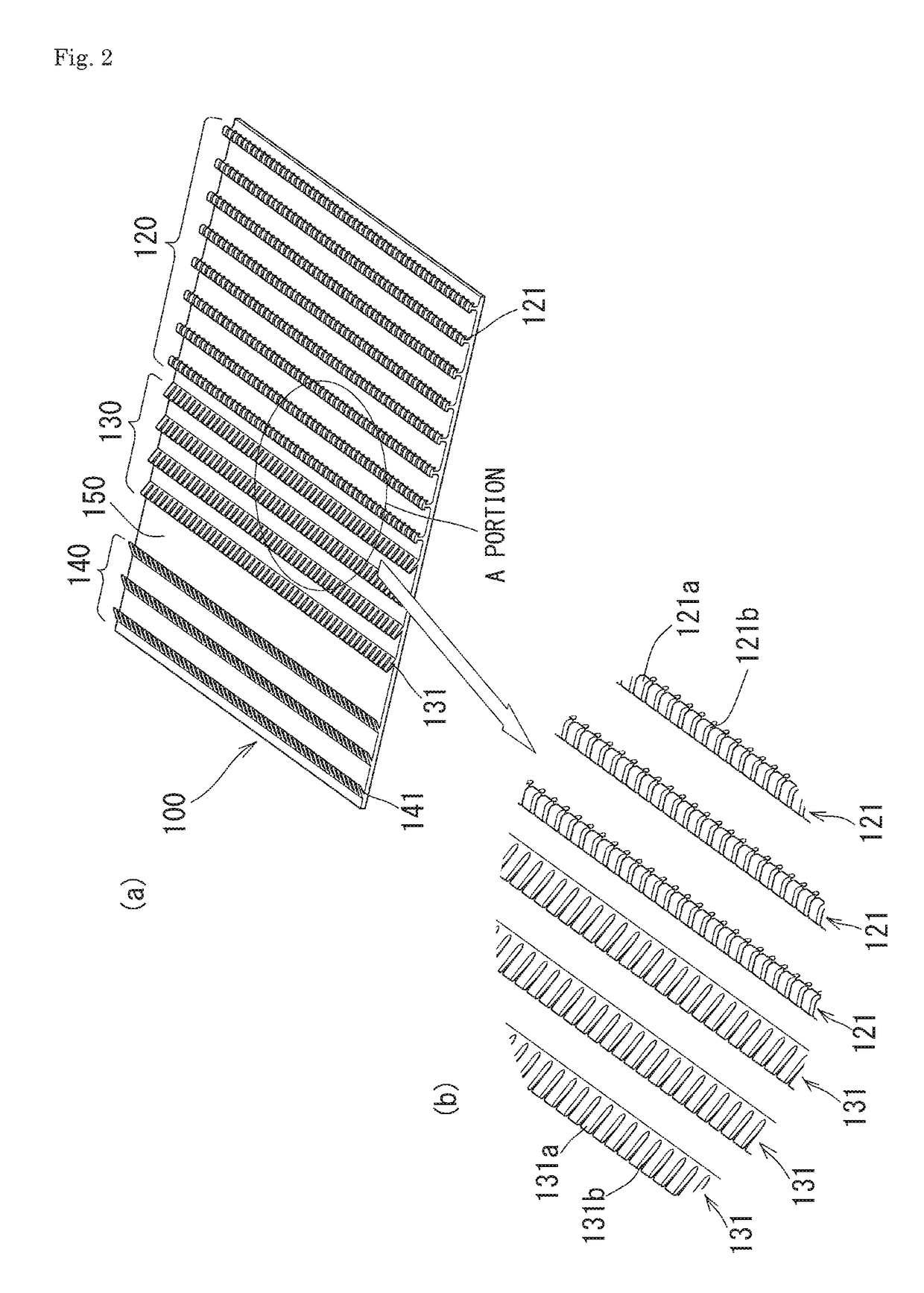
The present invention provides a surface fastener made of synthetic resin that is used to join a covering member to a cushioning member in a seat structure. The surface fastener has the advantage of high resistance to pressure and a comfortable feel compared to traditional surface fasteners made of woven fabric. The engagement elements are arranged in rows and each independently protrude, resulting in a cushioning member that is covered with the covering member via the surface fastener. The resistance value of the surface fastener is higher than that of ordinary surface fasteners but the static load characteristic of the surface fastener when stacked on the cushioning member is similar to that of the cushioning member without the surface fastener. The spring constant of the surface fastener is close to that of the human muscle, making it comfortable and less likely to cause a feeling of foreignness. The surface fastener joins the covering member to the cushioning member at a boundary portion that is easy to bend, increasing the engagement force in the surface fastener. This prevents the outer layer member from easily coming off the cushioning member.

Problems solved by technology

If they are designed so that the engagement force works in a balanced manner in all the directions, it becomes difficult to set the engagement force extremely high.

Method used


Image

  • Surface fastener, cushioning structure, and seat structure
  • Surface fastener, cushioning structure, and seat structure
  • Surface fastener, cushioning structure, and seat structure

Examples


application examples

of Present Invention

[0086]The surface fastener of the present invention exhibits a high engagement force as described above. Therefore, it can be used not only for fixing the covering member to the cushioning member but also as a means for fixing a floor mat 1000 laid on a floor of a vehicle such as an automobile as illustrated in FIGS. 11(a) to (d), for instance. A metal surface of a floor surface of especially an automobile is not exposed as it is but is covered with a floor carpet 1100, and thus the engagement elements 121a, 131a, 141a of the surface fastener 100 are engageable therewith. Specifically, the surface fasteners 100 illustrated in FIG. 2 and FIG. 3 are stacked on the floor mat, with the rear surfaces of the bases 110 being on the rear surface of the floor mat, and are fixed to the floor mat by sewing, bonding, or the like, preferably by sewing, and the engagement elements 121a, 131a, 141a are engaged with the floor carpet 1100. A possible alternative structure, not il...


PUM

PropertyMeasurementUnit
Lengthaaaaaaaaaa
Lengthaaaaaaaaaa
Fractionaaaaaaaaaa

Abstract

A surface fastener formed of a synthetic resin and in which a base with a 0.1 to 0.9 mm thickness and engagement element groups including engagement elements with a 0.2 to 0.8 mm protrusion height are integrally molded, and engagement element rows are composed of the plural engagement elements arranged in a row direction and each protruding independently. A cushioning member is covered with a covering member via the surface fastener. A resistance value of the surface fastener by itself as measured by a handle-o-meter method conforming to the JIS L 1096 E method is 80 to 150 g, whereas a load-deflection characteristic when a pressure is applied to an overlapping portion of the stacked surface fastener and cushioning member by a pressure plate with a 30 mm diameter approximates a similarly measured load-deflection characteristic of the cushioning member by itself.

Description

TECHNICAL FIELD[0001]The present invention relates to a surface fastener, a cushioning structure covered with a covering member via the surface fastener, and a seat structure using the cushioning structure.BACKGROUND ART[0002]As is disclosed in Patent Document 1, a hook surface fastener has protruding engagement elements in a hook shape, a mushroom shape, or an arrowhead shape formed to protrude on a base. The protruding engagement elements are ordinarily formed to stand substantially vertically from the base. Accordingly, in an engaged state with an engagement counterpart (loop surface fastener, or the like), the surface fastener exhibits a certain engagement force against tensile forces both in a shear direction (direction horizontal to the surface) and the vertical direction.[0003]Patent Document 2 and Patent Document 3 each disclose a surface fastener including protruding engagement elements tilting in one direction on a base to thereby have an engagement force that differs depe...

Claims


Application Information

Patent Timeline
IPC IPC(8): B60N2/58A44B18/00B29C47/00B29C48/12
CPCB60N2/5833A44B18/0073B60N2/5883A44B18/0049A44B18/0061B29C47/003B29K2081/06B29K2067/006B29L2031/58B29C48/12B29K2075/00B29K2105/04
Inventor FUJITA, ETSUNORIOGURA, YUMIKAWASAKI, SEIJIWAGATA, SHIGEKIHIGASHINAKA, YUKITOSHIONO, SATORUTANOKURA, TOORU
Owner DELTA TOOLING CO LTD
Learn More