Fastening device

a technology of fastening device and fastening rod, which is applied in the direction of fastening means, screws, threaded fasteners, etc., can solve the problems of affecting the entire detachment operation, affecting requiring a longer time for conventional fastening devices, so as to improve the convenience of installation or detachment, facilitate the operation of the fastening device, and improve the convenience of installation or detach

Active Publication Date: 2018-07-19
HANWIT PRECISION IND LTD
View PDF5 Cites 7 Cited by
  • Summary
  • Abstract
  • Description
  • Claims
  • Application Information

AI Technical Summary

Benefits of technology

[0008]An objective of the present disclosure is to provide a fastening device including a sleeve, a rotary knob device and a drive cap. The sleeve is formed with a through-hole inside, and the through-hole defines a rotation space having a larger diameter at a side thereof, a fastening part is formed on an outer side of the sleeve corresponding in position to the rotation space, and a position-limiting ring is formed on other side of the sleeve opposite to the fastening part and has a larger diameter, and the position-limiting ring comprises a first position-limiting fastening groove, two second position-limiting fastening grooves formed at two opposite sides of the first position-limiting fastening groove, and a protrusion ring formed between the two second position-limiting fastening grooves and having an extended outer diameter, and the first position-limiting fastening groove, the two second position-limiting fastening grooves and the protrusion ring are formed on a periphery of the position-limiting ring. The rotary knob device includes a rod head disposed above the sleeve and a fastening member downwardly extended from a bottom surface of the rod head and inserted through the through hole, the fastening member comprises a rod, and a fastening part formed at a lower part of the rod and movably disposed in the rotation space, and the rotary knob device includes an elastic member mounted outside the fastening member and elastically abutted with the bottom surface of the rod head and an inner wall of the through-hole. The rod head of the rotary knob device is assembled in an assembly space of the drive cap, and the assembly space is formed with a sliding inner hole for covering the position-limiting ring of the sleeve, and the position-limiting ring is longitudinally movable in the sliding inner hole, and the sliding inner hole is formed with a long protrusion rod and two short protrusion rods disposed on a sidewall thereof and configured to align and engage with a first position-limiting fastening groove and two second position-limiting fastening grooves of the position-limiting ring. When the drive cap is pressed for locking, the drive cap can be bi-directionally rotated axially, and after the rotary knob device is locked, the protrusion ring blocks the long protrusion rod formed on the inside wall of the sliding inner hole, so that the drive cap can only unidirectionally rotate back to perform unlocking process. As a result, the user can effortlessly recognize whether the rotary knob device is in the locked or unlocked state according to hand feeling of operating the drive cap, thereby achieve purpose of intuitional, simple and quick operation, and improving convenience in installation or detachment.
[0009]Another objective of the present disclosure is that the long protrusion rod and the two short protrusion rods formed in the sliding inner hole of the drive cap are respectively longitudinally movable along the first position-limiting fastening groove and the two second position-limiting fastening grooves of the position-limiting ring of the sleeve, and the drive cap can drive the fastening part at an end of fastening member of the rotary knob device to longitudinally move into or out of the rotation space of the sleeve, so that the user can simply and easily operate the fastening device to lock or unlock the predetermined first plate and second plate without using any hand tools, thereby achieving the purpose of time and effort saving.
[0010]Another objective of the present disclosure is that, before the drive cap is pressed down, the protrusion ring of the position-limiting ring can block the two short protrusion rods formed on the inside wall of the sliding inner hole, to prevent the drive cap from axially rotating, so that the fastening part at the end of the fastening member can reliably pass through the through hole of the second plate; and, after the drive cap is pressed down to rotate, the protrusion ring can block the long protrusion rod formed on the inside wall of the sliding inner hole, and the drive cap can only be rotated back in the reverse direction, thereby achieving the purpose of improving usage fluency.
[0011]Another purpose of the present disclosure is that a length of the fastening member is higher than that of the sleeve, and when the fastening member of the rotary knob device is driven by the drive cap to longitudinally move, the fastening part of the fastening member is extended out of the sleeve, and at this time, if the second plate is not placed under the first plate, the fastening part of the fastening member is retrieved into the sleeve subject to the recovery action of the elastic member, so that the fastening device is not locked with the first plate. As a result, the user can know whether the second plate to be locked is placed under the first plate according to the hand feeling in operation, thereby providing nice anti-mistaking effect and achieving the purpose of improving assembly reliability.

Problems solved by technology

However, if a user forgets to carry suitable hand tools, entire detachment operation may be affected, so a manufacturer develops a fastening device, and the user can rotate this fastening device by hand to fasten or separate the plates.
Besides that, usage of the conventional fastening device takes a longer time and is inconvenient, and the outer cap C also must be processed to form the indication part C4 on the upper surface thereof, to make the user understand the direction for locking and unlocking the fastening device, which may cause more cost due to the processing operation.
Furthermore, the general fastening devices are usually used in chassis of telecommunications cabinet, industrial computer, machine tool, server and so on, and the user is not easy to see and recognize the indication part C4 of the outer cap C of the conventional fastening device under the dark environment inside the chassis, so the user can determine whether the fastening device is in locked or unlocked state by only operation feeling, but the feelings of operating the fastening device in the locked state and the unlocked state are the same, which causes inconvenience in use.

Method used


Image

  • Fastening device
  • Fastening device
  • Fastening device

Examples


Embodiment Construction

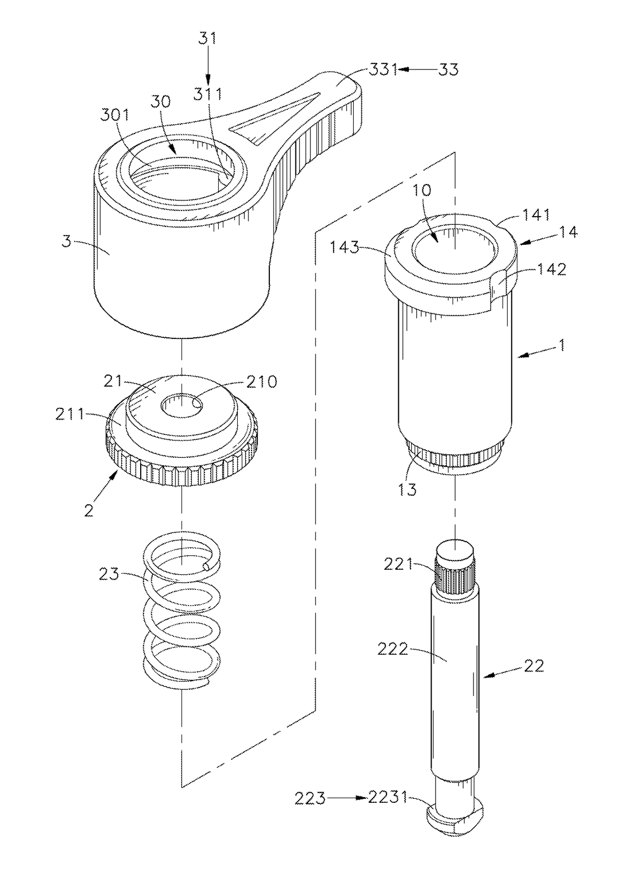
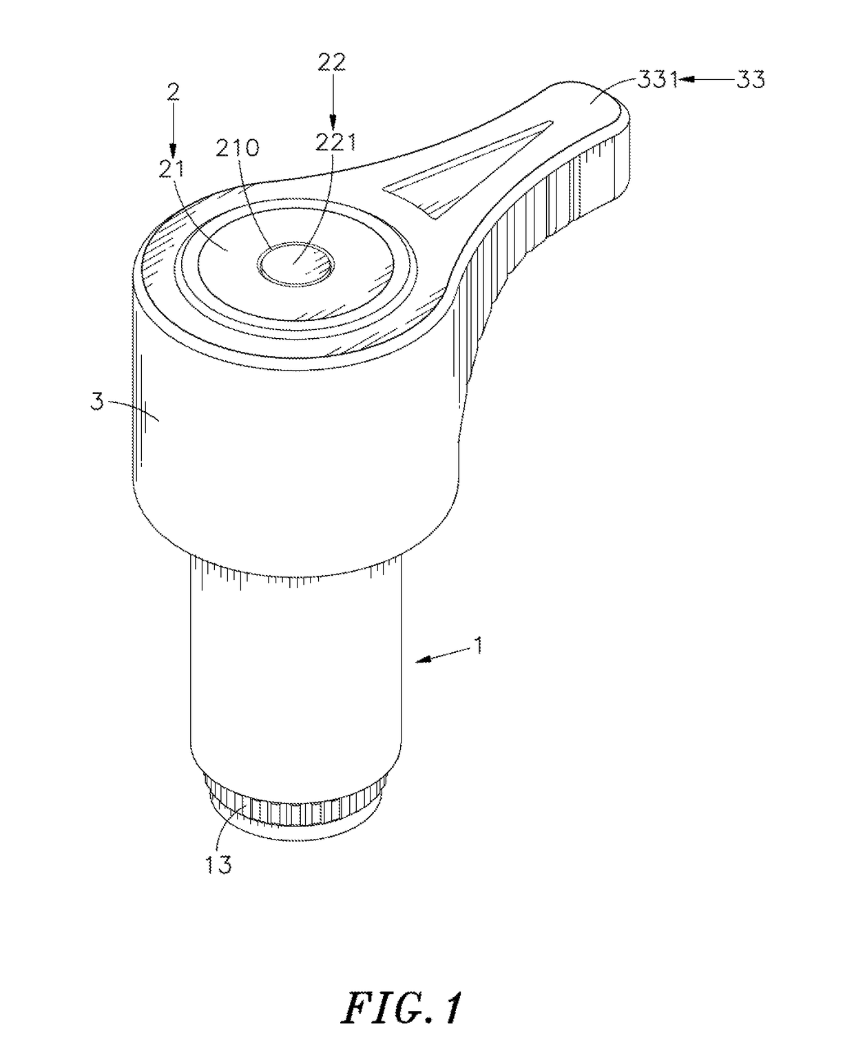
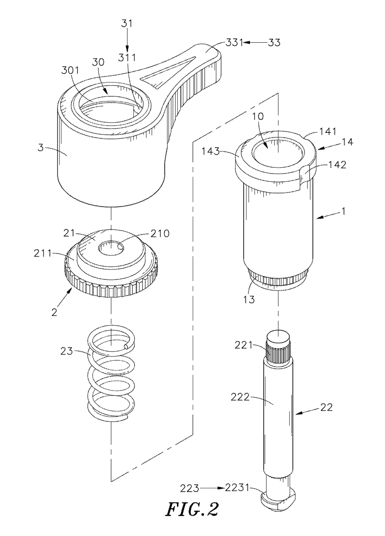
[0025]The following embodiments of the present invention are herein described in detail with reference to the accompanying drawings. These drawings show specific examples of the embodiments of the present invention. It is to be understood that these embodiments are exemplary implementations and are not to be construed as limiting the scope of the present invention in any way. Further modifications to the disclosed embodiments, as well as other embodiments, are also included within the scope of the appended claims. These embodiments are provided so that this disclosure is thorough and complete, and fully conveys the inventive concept to those skilled in the art. Regarding the drawings, the relative proportions and ratios of elements in the drawings may be exaggerated or diminished in size for the sake of clarity and convenience. Such arbitrary proportions are only illustrative and not limiting in any way. The same reference numbers are used in the drawings and description to refer to...


PUM


Abstract

The present disclosure illustrates a fastening device. In the fastening device, a sleeve is formed with a through-hole which defines a rotation space, a position-limiting ring is formed on the sleeve and includes a first position-limiting fastening groove and two second position-limiting fastening grooves; a fastening member is formed on a bottom surface of a rod head of a rotary knob device dispose outside the sleeve; a long protrusion rod and two short protrusion rods are formed in the sliding inner hole of the assembly space and respectively aligned with the first position-limiting fastening groove and the two second position-limiting fastening grooves. During locking operation, the drive cap can be bi-directionally rotated; and during unlocking operation, the drive cap can only be unidirectionally rotate, thereby achieving the purpose of easily recognize the locked or unlocked state according to different hand feeling in operation.

Description

[0001]This application is a Continuation-In-Part of application Ser. No. 15 / 409,376, filed on Jan. 18, 2017, for which priority is claimed under 35 U.S.C. § 120, the entire contents of which are hereby incorporated by reference.BACKGROUND OF THE INVENTION1. Field of the Invention[0002]The present disclosure relates to a fastening device, more particularly to a fastening device in which a drive cap disposed outside a sleeve can be pressed down to bi-directionally rotate to drive a rotary knob device inside the sleeve to perform a locking operation; in the other hand, in order to unlock the rotary knob device, the drive cap can only be unidirectionally rotate in a reverse direction. As a result, the user can determine whether the fastening device is in the locked state or the unlocked state according to hand feeling of rotating the fastening device, so as to achieve a purpose of intuitional, simple and quick operation.2. Description of the Related Art[0003]Conventionally, in order to ...

Claims


Application Information

Patent Timeline
Patent Type & Authority Applications(United States)
IPC IPC(8): F16B39/24F16B5/02
CPCF16B39/24F16B5/0266F16B5/0208F16B19/109
Inventor WU, MING-DECHANG, CHING-KAI
Owner HANWIT PRECISION IND LTD
Why Eureka
Try Eureka