Liquid crystal lens, manufacturing method thereof and curved display device

Active Publication Date: 2018-07-19
BOE TECH GRP CO LTD +1
View PDF7 Cites 0 Cited by
  • Summary
  • Abstract
  • Description
  • Claims
  • Application Information

AI Technical Summary

Benefits of technology

[0013]The existing liquid crystal lens for achieving a curved display effect comprises: liquid crystals, as well as a first electrode and a second electrode for driving the liquid crystals to achieve curved display. Specifically, one of the first electrode and the second electrode is generally a plurality of independent electrodes separate from each other, and the other is a plate electrode. Besides, the first electrode and the second electrode are both located in respective planes (which planes are parallel with the substrates separately). It has been found by the inventors that in positions between independent electrodes, the electric field is comparatively weak. This results in fluctuations in the refractive index of the liquid crystals in these

Problems solved by technology

However, such a bended design can only make a user located in a central viewing position feel comfortable.
A viewer cannot achieve a similar effect when located in other viewing positions.
Also, the central viewing position is usually not adjustable upon actual needs.
Besides, the display device manufactured in a curved or bended shape often needs to occup

Method used


Image

  • Liquid crystal lens, manufacturing method thereof and curved display device
  • Liquid crystal lens, manufacturing method thereof and curved display device
  • Liquid crystal lens, manufacturing method thereof and curved display device

Examples


Embodiment Construction

[0023]The technical solutions in the embodiments of this disclosure will be described below clearly and completely with reference to the drawings. Apparently, the described embodiments are only part of the embodiments of this disclosure, instead of all. Based on the embodiments of this disclosure, all other embodiments, obtainable by those having ordinary skills in the art without inventive efforts, shall fall within the protection scope of this disclosure.

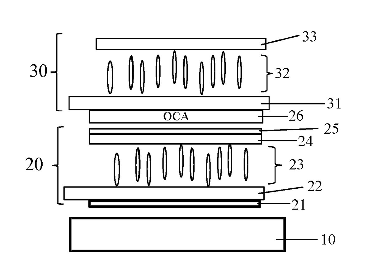
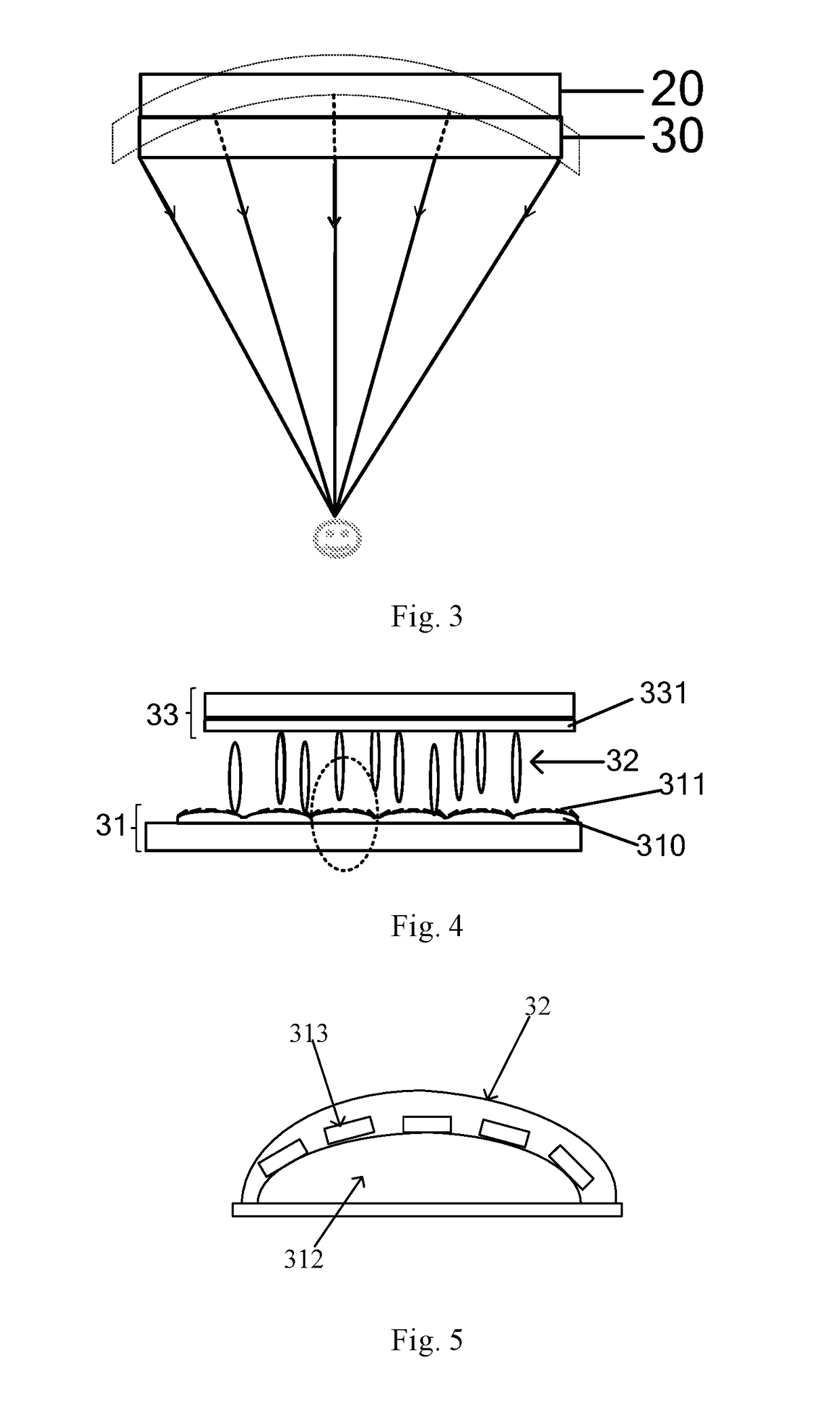
[0024]In the drawings, components involved in the embodiments of this disclosure are indicated by the following reference signs. Specifically: 10—backlight module, 20—display panel, 30—liquid crystal lens, 26—optical clear adhesive, 21—lower polarizer, 22—array substrate, 23—liquid crystal, 24—color filter substrate, 25—upper polarizer, 31—first substrate, 32—liquid crystal, 33—second substrate, 310—elevation layer, 311—first electrode, 312—bump, 313—independent electrode, and 331—second electrode.

[0025]At present, a flat display ...


PUM


Abstract

A liquid crystal lens, a manufacturing method and a corresponding curved display device are disclosed. The liquid crystal lens is configured to be adhered over a flat display device for achieving curved display, and includes liquid crystals, a first electrode and a second electrode for driving the liquid crystals, and an elevation layer. The first electrode includes a plurality of independent electrodes separate from each other, each independent electrode being arranged on the elevation layer. The elevation layer is further configured such that each independent electrode is located in a different position along a thickness direction of the elevation layer.

Description

[0001]The present application is the U.S. national phase entry of PCT / CN2017 / 070732, with an international filling date of Jan. 10, 2017, which claims the benefit of Chinese Patent Application No. 201610202960.5, filed on Apr. 1, 2016, the entire disclosures of which are incorporated herein by reference.FIELD[0002]This disclosure relates to the field of display, and in particular to a liquid crystal lens, a manufacturing method thereof and a corresponding curved display device.BACKGROUND ART[0003]In conventional curved display, a display device is physically manufactured in a curved or bended shape, so as to have all different positions of the display device to face human eyes, thereby obtaining an optimal viewing angle experience. However, such a bended design can only make a user located in a central viewing position feel comfortable. A viewer cannot achieve a similar effect when located in other viewing positions. Also, the central viewing position is usually not adjustable upon ...

Claims


Application Information

Patent Timeline
IPC IPC(8): G02F1/1343G02F1/03G02F1/133G09G3/36
CPCG02F1/1343G02F1/0311G02F1/13306G09G3/36G02F1/134309G02F1/29G09G3/003G09G2300/023G02F1/13471G02F1/294G09G3/03G09G2380/02
Inventor WANG, LEICHEN, XIAOCHUANZHAO, WENQINGWANG, QIANXU, RUIYANG, MINGGAO, JIANLU, PENGCHENGNIU, XIAOCHENLI, CHANGFENG
Owner BOE TECH GRP CO LTD
Why Eureka
Try Eureka