Lifting device for picking up a member from the bottom of the sea

Active Publication Date: 2018-07-26
IHC HOLLAND NV
View PDF0 Cites 2 Cited by
  • Summary
  • Abstract
  • Description
  • Claims
  • Application Information

AI Technical Summary

Benefits of technology

[0030]The floating piston, leaking piston and further pressure chamber together enable to provide spring action at the engagement member and active operation of the engagement member while kee

Problems solved by technology

Incorporating a free weight in the lifting device complicates the design and a drawing line is cumbers

Method used


Image

  • Lifting device for picking up a member from the bottom of the sea
  • Lifting device for picking up a member from the bottom of the sea
  • Lifting device for picking up a member from the bottom of the sea

Examples


Embodiment Construction

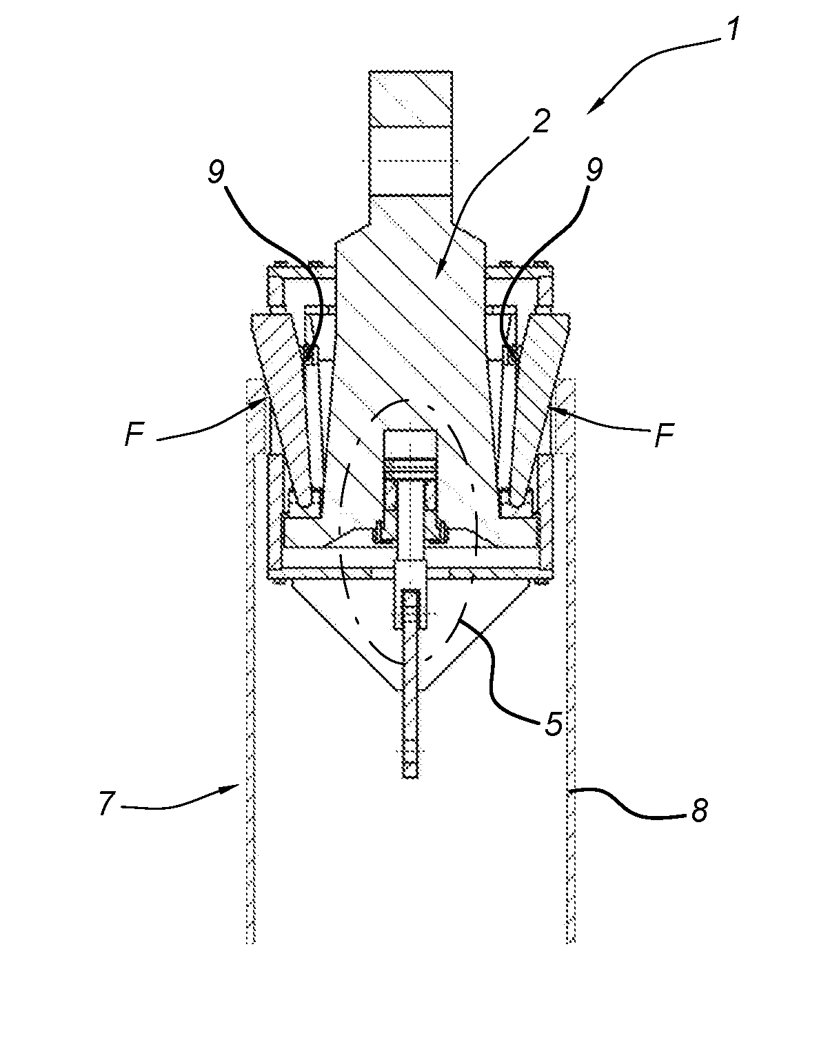
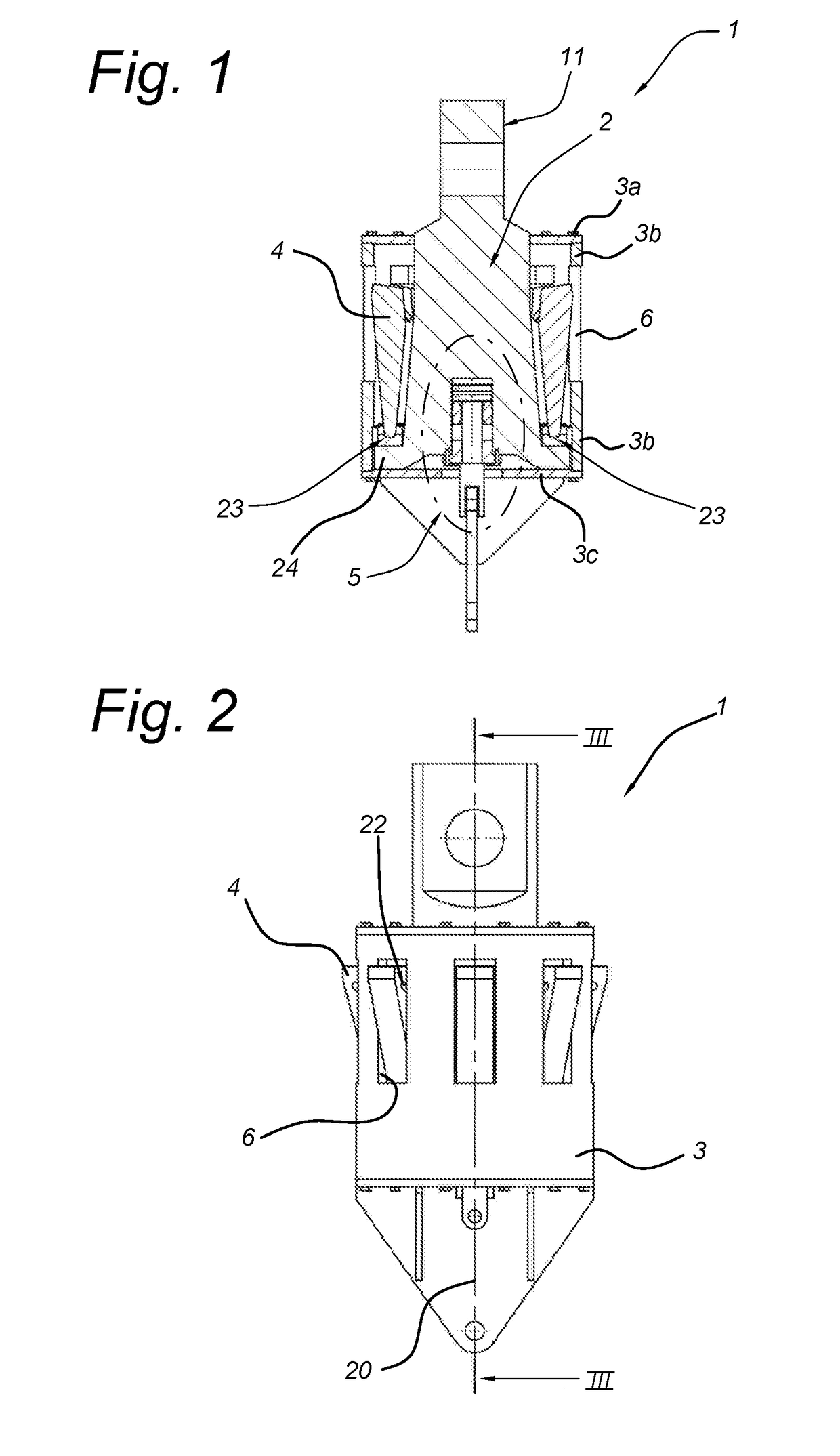
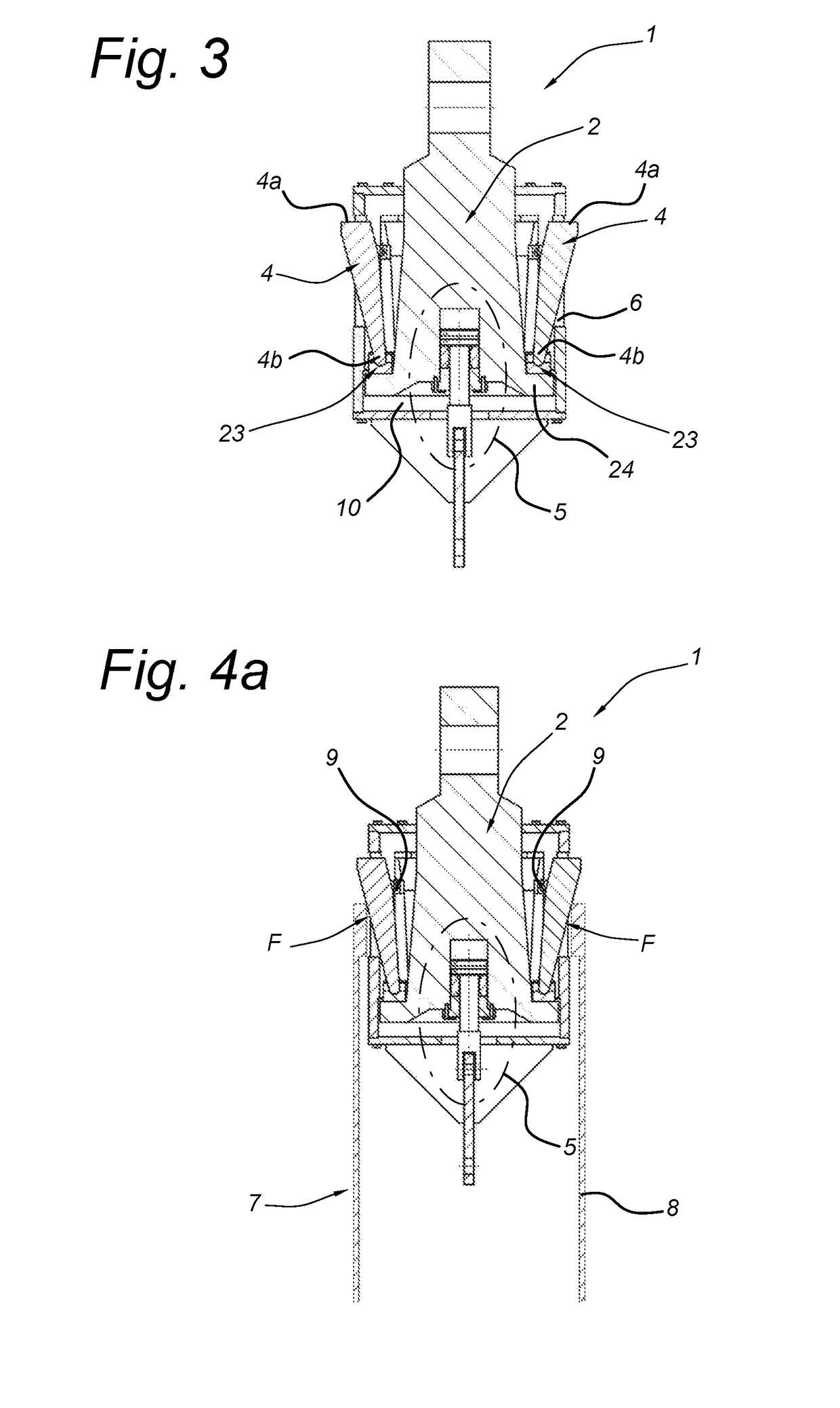
[0047]In the FIGS. 1-3 an embodiment of the lifting device 1 according to the invention is shown.

[0048]The lifting device 1 is suitable for picking up a member 7 from the bottom of the sea.

[0049]The lifting device 1 comprises a central body 2. The central body 2 extending along a central axis 20 of the lifting device 1. The central body is at its trailing end provided with a means 11 for connection to a hoist cable which is not shown. Here, the central body 2 is massive however it may also be constructed from plate material.

[0050]The lifting device 1 comprises a housing 3. The housing 3 is configured to be introduced into a cavity 21 of the member 7 to be picked up. The housing 3 accommodates a major part of the body 2. Here, the housing 3 is formed by a cylindrical housing portion 3b, a top lid 3a and a housing bottom 3c. The body 2 extends through the top lid 3a.

[0051]The body 2 and the housing 3 are moveable arranged with respect to each other along the central axis 20 of the li...


PUM


Abstract

The invention relates to a lifting device for picking up a member from the bottom of the sea, the lifting device comprising;
    • a body extending along a central axis of the lifting device and having means for connection to a hoist cable,
    • a housing configured to be at least partially introduced into a cavity of the member to be picked up and accommodating at least a part of the body and wherein the body and the housing are moveable with respect to each other along the central axis of the lifting device.

Description

BACKGROUND[0001]The present invention relates to a lifting device for picking up a member from the bottom of the sea, the lifting device comprising a body, a housing and an engagement member coupled with the body and the housing such that the engagement member is moveably arranged to move in a radial direction with respect to the central axis. An example of this type of lifting device of the present invention is referred to as to internal lifting tool in the field.[0002]Such a lifting device is known from GB1577778 which relates to lifting devices for tubular piles. GB1577778 provides a pipe lifting device having a plurality of latches movably mounted on the body and moveable between retracted positions and extended positions in which the latches project laterally of the body. The latches can be operated by a weight means and a drawing line.[0003]Incorporating a free weight in the lifting device complicates the design and a drawing line is cumbersome in use during operations at the ...

Claims


Application Information

Patent Timeline
IPC IPC(8): E21B19/06E21B31/20E21B41/00F16F9/02
CPCE21B19/06E21B31/20E21B41/0007F16F9/0218
Inventor MULDERIJ, KLAAS-JAN
Owner IHC HOLLAND NV
Why Eureka
Try Eureka