Electronic Timepiece

Active Publication Date: 2019-10-24
SEIKO EPSON CORP
View PDF0 Cites 3 Cited by
  • Summary
  • Abstract
  • Description
  • Claims
  • Application Information

AI Technical Summary

Benefits of technology

The invention is a solar panel for electronic timepieces that prevents blocking of light, improves power generation, and reduces antenna performance during both reception and transmission. This results in a reduction in parts count for the timepiece.

Problems solved by technology

As a result, the performance of the solar panel decreases.
This configuration can suppress a decrease in antenna performance because all of the outside circumference part of the radiating electrode is located outside the power generating part.

Method used


Image

  • Electronic Timepiece
  • Electronic Timepiece
  • Electronic Timepiece

Examples


embodiment 1

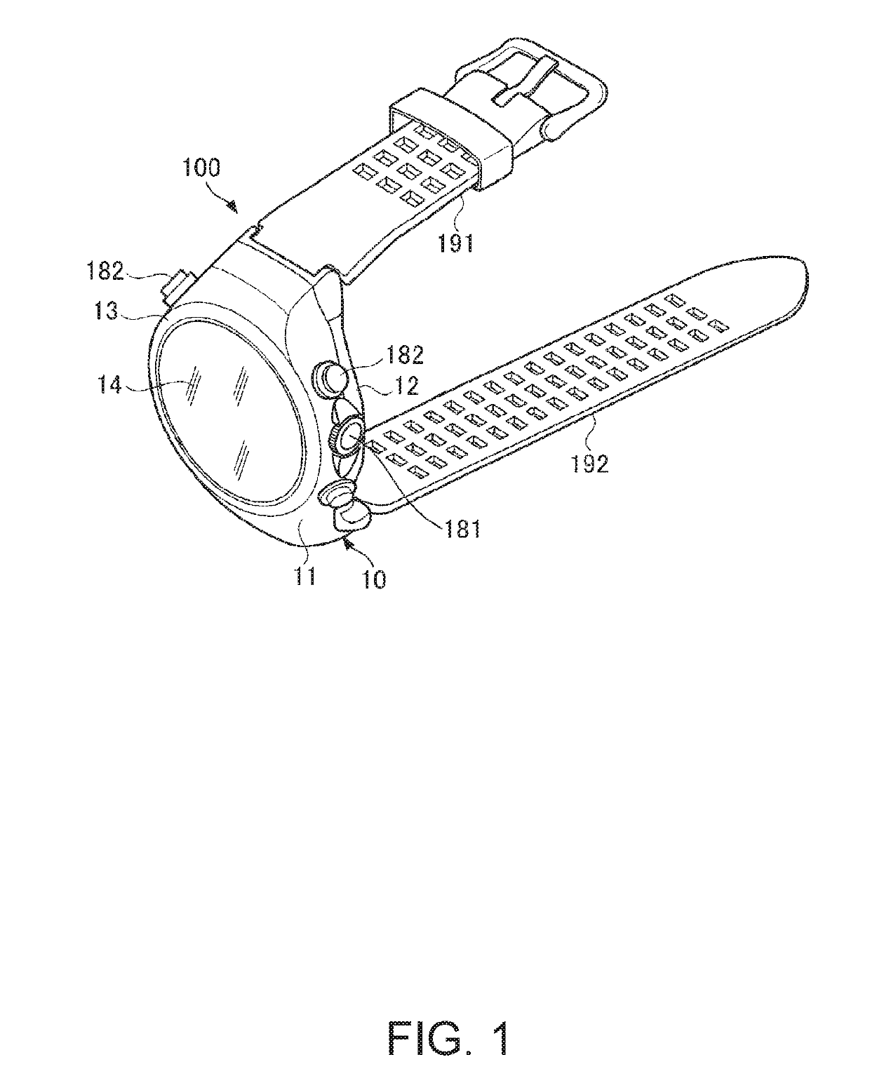
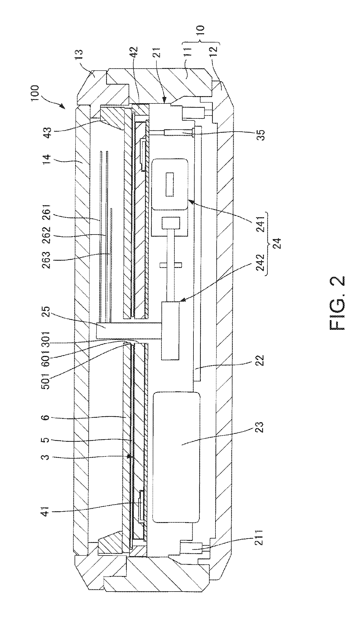
[0031]FIG. 1 is an oblique view of an electronic timepiece according to a first embodiment of the invention. FIG. 2 is a section view of the electronic timepiece shown in FIG. 1.

[0032]The electronic timepiece 100 shown in FIG. 1 is configured as a wristwatch type device typically worn on the user's wrist. This electronic timepiece 100 has the functions of a wristwatch that adjusts the internal time by receiving satellite signals from GPS satellites, and the ability to calculate the current location using GPS time information and satellite orbit information.

[0033]As shown in FIG. 1, the electronic timepiece 100 has a case 10, an optically transparent, flat cover 14 attached to the case 10, and a pair of belts, belt 191 and belt 192, as members used to hold the electronic timepiece 100 on the user's wrist.

[0034]Note that below, the cover 14 side of the electronic timepiece 100 is referred to as the face side or top side, and the opposite side that is worn in contact with the user's wr...

embodiment 2

[0093]A second embodiment of the invention is described next. FIG. 5 is a plan view of the solar panel and antenna pattern in an electronic timepiece according to a second embodiment of the invention.

[0094]This embodiment is the same as the first embodiment described above other than the configuration of the solar panel. The following description of the second embodiment focuses on the differences with the embodiment described above, and further description of like parts is omitted. Like parts in this embodiment and the embodiment described above are also identified by the same reference numerals in FIG. 5.

[0095]The solar panel 5A shown in FIG. 5 has a first power generating part 51A, a second generating part 54, a first non-generating part 521, a second non-generating part 522, and multiple leads 55. Note that in FIG. 5 the first non-generating part 521 and second non-generating part 522 are indicated by a dotted pattern.

[0096]The first power generating part 51A is configured ident...

embodiment 3

[0112]A third embodiment of the invention is described next. FIG. 6 is a plan view of the solar panel and antenna pattern in an electronic timepiece according to a third embodiment of the invention. FIG. 7 is an enlarged view of part of the electronic timepiece according to the third embodiment of the invention.

[0113]This embodiment is the same as the first embodiment described above other than the configuration of the solar panel and the configuration of the holding member. The following description of the third embodiment focuses on the differences with the embodiments described above, and further description of like parts is omitted. Like parts in this embodiment and the embodiments described above are also identified by the same reference numerals in FIG. 6 and FIG. 7.

[0114]As shown in FIG. 6, the solar panel 5B has a power generating part 51, but does not have the non-generating part 52 of the first embodiment.

[0115]The size of the solar panel 5B in plan view is smaller than th...


PUM


Abstract

An electronic timepiece suppresses loss of power generating performance of a solar panel, and suppresses drop loss of antenna performance. The electronic timepiece has a pivot; a dial that transmits a light through which the pivot passes; an antenna having a radiating electrode through which the pivot passes; and a solar panel through which the pivot passes and which is disposed between the dial and the radiating electrode. The solar panel has a power generating part that converts light to electrical energy, and is disposed, in a plan view through the thickness direction of the dial, superimposed with the radiating electrode. Part or all of the outside circumference of the radiating electrode is disposed outside the power generating part in plan view.

Description

BACKGROUND1. Technical Field[0001]The present invention relates to an electronic timepiece.2. Related Art[0002]Electronic timepieces having an antenna for receiving satellite signals, and a solar cell that converts light energy to electrical energy, are known from the literature.[0003]JP-A-2012-93211 describes an electronic timepiece having an antenna and a solar panel. The antenna has a radiating electrode and a ground electrode with a dielectric disposed therebetween. In this electronic timepiece, the radiating electrode is configured as a transparent electrode made of ITO (Indium Tin Oxide), for example, and the solar panel is disposed between the radiating electrode and the dielectric. This configuration enables light to pass through the radiating electrode to the solar panel, enabling photovoltaic generation. In addition, because the radiating electrode is between the solar panel and the crystal of the electronic timepiece, attenuation of satellite signals to the radiating elec...

Claims


Application Information

Patent Timeline
IPC IPC(8): G04C10/02G04B19/24G04G21/04H01Q9/04H01Q1/27
CPCG04G21/04G04B19/24G04C10/02H01Q1/273H01Q9/0421H01Q9/42H01Q9/0428G04R60/12Y02E10/50
Inventor SAWADA, AKIHIRO
Owner SEIKO EPSON CORP
Why Eureka
Try Eureka