LED aircraft anticollision beacon

Inactive Publication Date: 2007-07-19
WHELEN ENGINEERING COMPANY
View PDF12 Cites 46 Cited by
  • Summary
  • Abstract
  • Description
  • Claims
  • Application Information

AI Technical Summary

Benefits of technology

[0011] An efficient LED anticollision beacon is achieved by employing circumferential reflecting troughs to re-direct off axis light into the desired radiation pattern. Capturing more light from ea

Problems solved by technology

However, flashers and rotating beacons suffer from limited life due to lamp burnout and mechanism wear.
The amount of light emitted from these anticollision lights is also relatively low, affording limited attention-getting light at distances from the aircraft.
Although more reliable than flashers and rotating beacons, strobe lights still suffer from a relatively short service life due to degradation of the strobe's electronic components from the continuous high-voltage charge and discharge cycles associated with each flash of the lamp.
This charge/discharge cycle also tends to produce RF noise that is undesirable for aircraft components.
However, Fleischmann teaches the use of light emitting diodes for interior cabin illumination, rathe

Method used


Image

  • LED aircraft anticollision beacon
  • LED aircraft anticollision beacon
  • LED aircraft anticollision beacon

Examples


Example

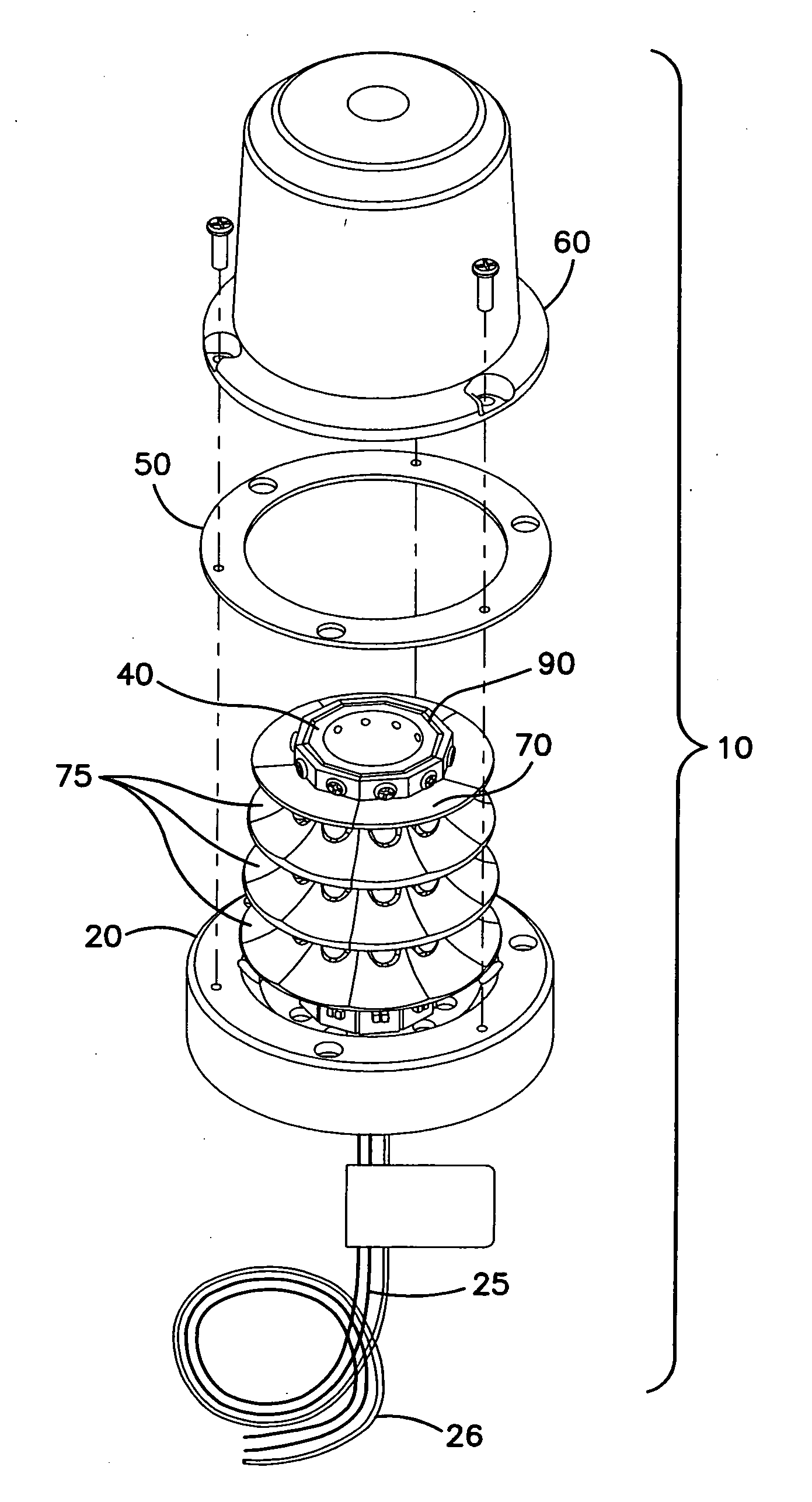
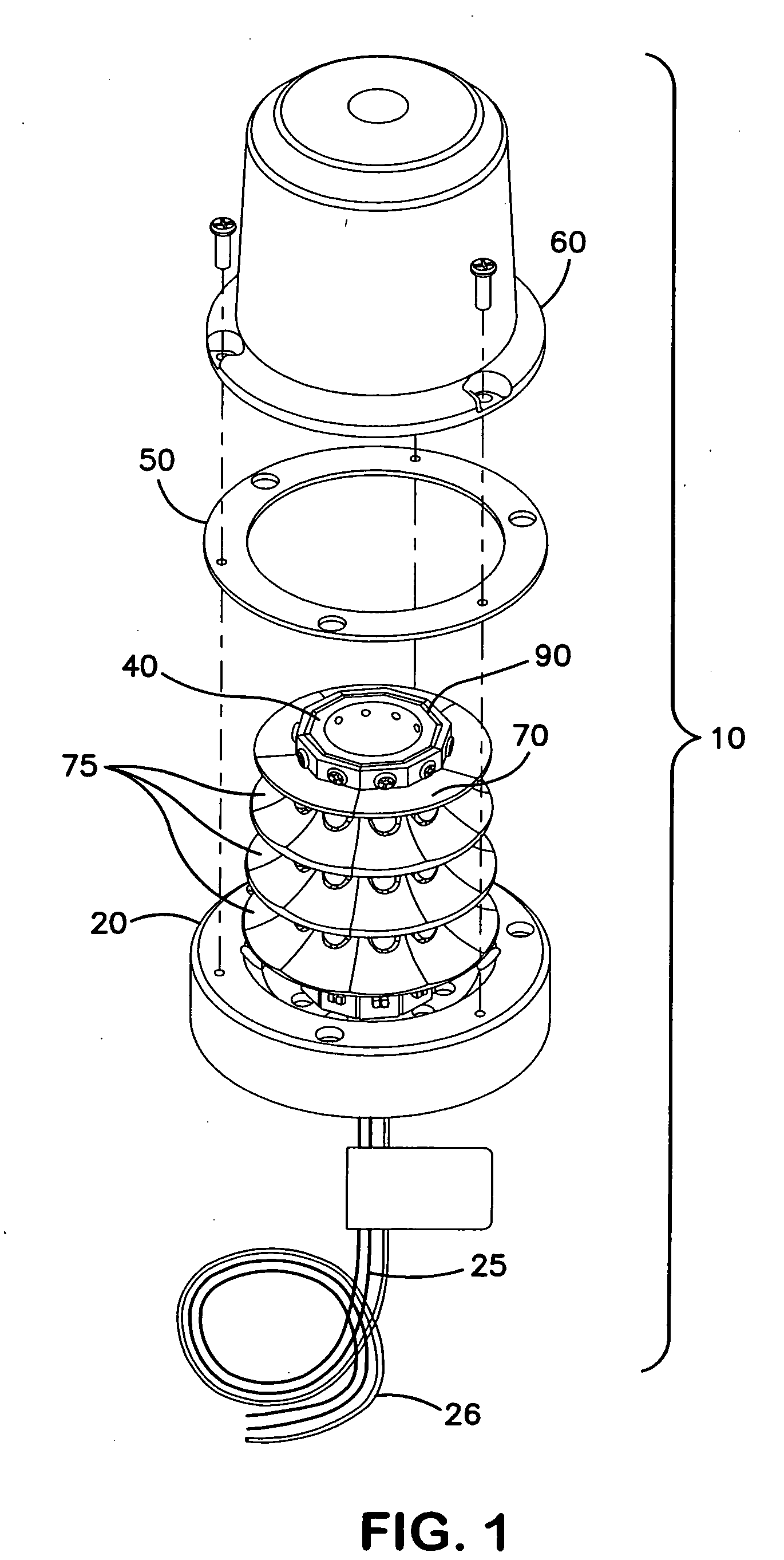
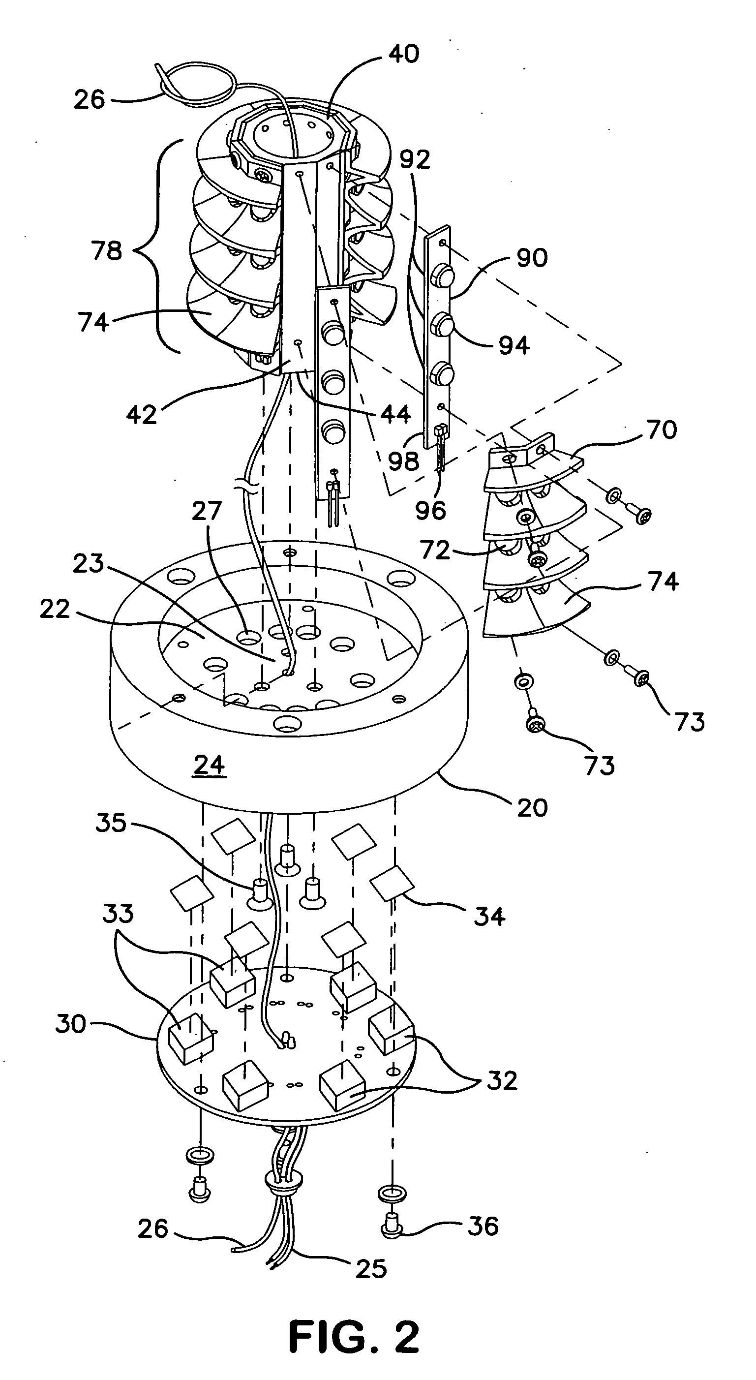
[0021] A first exemplary embodiment of an anticollision beacon illustrative of aspects of the present invention will be described with reference to FIGS. 1 and 2. FIG. 1 shows the assembled anticollision beacon 10 with the associated lens 60 and gasket 50. FIG. 2 is a detailed exploded view of the anticollision beacon 10. The configurations of the selected components and their assembled relationships are selected to provide an anticollision beacon that is extremely rugged and energy efficient while meeting all applicable performance standards.

[0022] To achieve the required lighting intensity and radiation pattern in a light source utilizing LEDs, it is necessary to use multiple discrete LEDs. One approach to using multiple LEDs to provide an anticollision beacon has been described with reference to U.S. Pat. No. 6,483,254. Heat dissipation is a major consideration because modern high-output LEDs produce significant quantities of heat and LEDs are temperature-sensitive components th...


PUM


Abstract

The exemplary aircraft anticollision beacons are constructed around a faceted aluminum support structure. The support structure has a cylindrical central post portion with an outside surface having at least six vertically oriented substantially planar faces. An array of LEDs is mounted in thermally conductive relationship on each face of the central post portion. Each LED is partially surrounded by a trough-shaped reflecting surface that re-directs off axis light into a horizontal plane. Adjacent trough-shaped reflecting surfaces combine to form annular reflecting troughs that extend around the circumference of the central post portion. The support structure defines a thermal pathway from the LEDs to a heat radiation surface on the base portion. The base portion is also configured to act as a heat sink for heat generating components of the LED driver circuits.

Description

CROSS REFERENCE TO RELATED APPLICATIONS [0001] This application is a continuation-in-part of Application Ser. No. 10 / 718,772, filed Nov. 21, 2003, now U.S. Pat. No. 7,079,041.BACKGROUND OF THE INVENTION [0002] 1. Field of the Invention [0003] This invention relates to a warning light and more specifically to an aircraft anticollision warning light employing light emitting diodes as a light source. [0004] 2. Description of the Related Art [0005] To prevent collisions, aircraft operating at night utilize a variety of lights to attract the attention of other aircraft operating in the same airspace. One such lighting system is the anticollision lighting system. A typical anticollision lighting system consists of flashing lights installed at several points on the aircraft to ensure that the lighted aircraft is visible to other aircraft operating in the vicinity. Anticollision lights are typically mounted on the aircraft's upper and lower fuselage, the tail, and the wingtips. Each of thes...

Claims


Application Information

Patent Timeline
IPC IPC(8): G09F9/33B64D47/06F21S8/00F21V29/00
CPCB64C2027/8236B64D47/06F21S10/06F21V29/004F21V29/74F21Y2101/02F21Y2111/005B64D2203/00F21W2111/06F21W2111/04F21V7/0083F21Y2107/30F21Y2115/10
Inventor FREDERICKS, THOMAS M.SMITH, TODD J.
Owner WHELEN ENGINEERING COMPANY
Why Eureka
Try Eureka