Pipe flange forming method

Active Publication Date: 2012-06-28
NAKAGAWA SANGYO
View PDF3 Cites 0 Cited by
  • Summary
  • Abstract
  • Description
  • Claims
  • Application Information

AI Technical Summary

Benefits of technology

[0007]It is an object of the present teachings to disclose an improved method for forming a flange on the open end of a pipe, e.g., a vehicle exhaust pipe, which reduces or eliminates the risk of bre

Problems solved by technology

However, since the coupling flanges 61 and 62 have to be affixed to the outer peripheries of the ends of the exhaust pipes 1 and 2 by welding in the above described known structure,

Method used


Image

  • Pipe flange forming method
  • Pipe flange forming method
  • Pipe flange forming method

Examples


Embodiment Construction

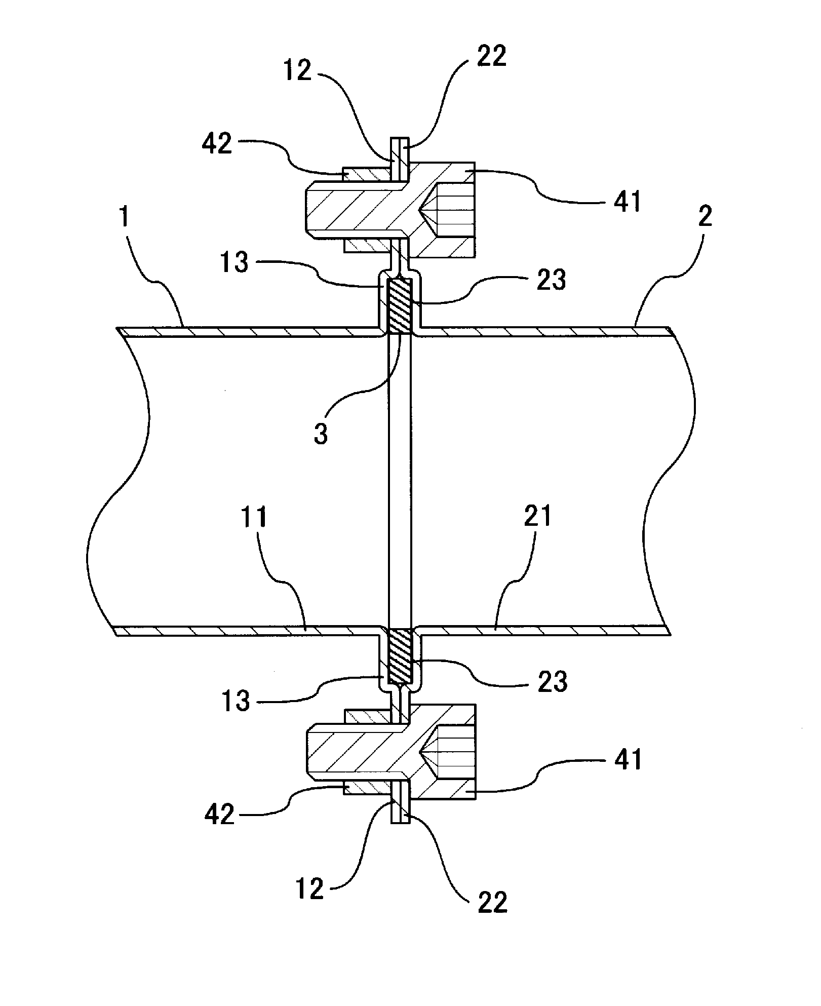
[0025]FIG. 1 shows a representative example of an upstream exhaust pipe 1 joined to a downstream exhaust pipe 2 via pipe-end flanges 12, 22 formed in accordance with the below-described method. More specifically, radially-outwardly-extending pipe-end flanges 12 and 22 are formed at an opening edge of an opening of a downstream end 11 of the upstream exhaust pipe 1 and at an opening edge of an opening of an upstream end 21 of the downstream exhaust pipe 2, respectively. The pipe-end flanges 12 and 22 are coupled together via bolts 41 and nuts 42 with a sealing member or gasket 3 interleaved in a space defined by recessed housing portions 13 and 23. The pipes 1, 2 and flanges 12, 22 are preferably formed of malleable steel, although other heat-resistant, malleable materials may be utilized for vehicle applications. For non-vehicle applications, the material forming the pipe 1, 2 and flange 12, 22 need not be heat-resistant, but it should be ductile or malleable, i.e. it should be plas...


PUM

PropertyMeasurementUnit
Diameteraaaaaaaaaa

Abstract

A method for forming a flange at an open end of a pipe comprises increasing the diameter of the open end of the pipe to form a radially-enlarged pipe wall. Radially-symmetric portions of the radially-enlarged pipe wall are then removed so as to form at least two opposing projecting portions, which are then bent outwardly so as to be at least substantially orthogonal to the pipe, thereby forming the flange on the pipe.

Description

BACKGROUND OF THE INVENTION[0001]1. Field of the Invention[0002]The present invention relates to a method for forming a flange on an open end of a pipe, e.g., for vehicle exhaust pipes.[0003]2. Description of the Related Art[0004]FIGS. 11 and 12 show an example of a known vehicle exhaust pipe coupling structure. In FIG. 12, approximately rhombic-shaped coupling flanges 61, 62 (see FIG. 11) are welded to the outer peripheral ends of an upstream exhaust pipe 1 and a downstream exhaust pipe 2, respectively. A gasket 63 disposed between the coupling flanges 61, 62 and the exhaust pipes 1 and 2 are joined using bolts 64 and nuts 65.[0005]Japanese Laid-Open Patent Publication No. H8-75063 discloses a connecting structure for an exhaust pipe, in which flanges are welded to the respective outer peripheries of a first exhaust pipe and a second exhaust pipe. The second exhaust pipe is fitted into the opening of one end of the first exhaust pipe. The flanges are joined by bolts and nuts.[0006]...

Claims


Application Information

Patent Timeline
IPC IPC(8): F16L23/00B21D19/00
CPCF16L23/024Y10T29/49398B21D19/08
Inventor NAKAGAWA, NORIAKI
Owner NAKAGAWA SANGYO
Why Eureka
Try Eureka