This helps you quickly interpret patents by identifying the three key elements:
Problems solved by technology
Method used
Benefits of technology
Benefits of technology
The invention relates to a small and efficient zip fastener that can be used to securely close small items. The male and female coupling parts are designed to be easily engaged and disengaged with minimal movement. The fastener is located close to the item, making it convenient for manufacturers and users, and can be used for both security and child-proofing purposes. The technical effects of the invention are improved security, efficiency, and flexibility.
Problems solved by technology
In particular, this may include an arrangement that is difficult to open with a single hand.
However, there are drawbacks to this system, related to the appearance of the locking pull tab and its exposed location.
Its unconventional shape may undesirably suggest it provides some security function and, particularly for manufacturers making a large range of products, for aesthetic reasons it may not be desired to use the locking pull tabs on all products, so conventional pull tabs cannot be eliminated to reduce the part count in the zip assembly.
A drawback of this arrangement is that it provides little or no casual security as moving one slider longitudinally with respect to the other to break the connection (and open the zip) is familiar and intuitive.
Method used
Image
Click on the blue label to locate the original text in one second.
Reading with bidirectional positioning of images and text.
Examples
first embodiment
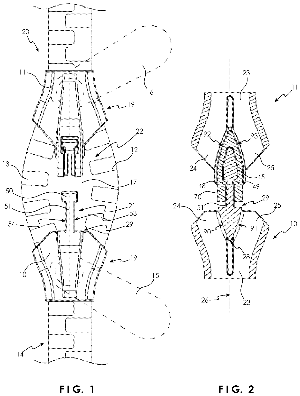
[0038]Referring to FIGS. 1 and 2, a zip fastener 20 generally comprises a first slider 10 and a second slider 11, both engaged with a pair of stringers 12, 13 (shown schematically) which may be connected together by means of meshed teeth 14, in the well-known manner Additionally, two pull tabs 15, 16 (shown in dashed outline) are provided, and they may be connected to an outer side of the respective slider 10, 11, to allow for improved purchase for the user to pull the sliders 10, 11 along the stringers 12, 13. Relative movement between the sliders 10, 11 along the stringers 12, 13 opens and closes the zip fastener 20 or, more specifically, opens and closes an opening 17 between the stringers 12, 13 and sliders 10, 11.
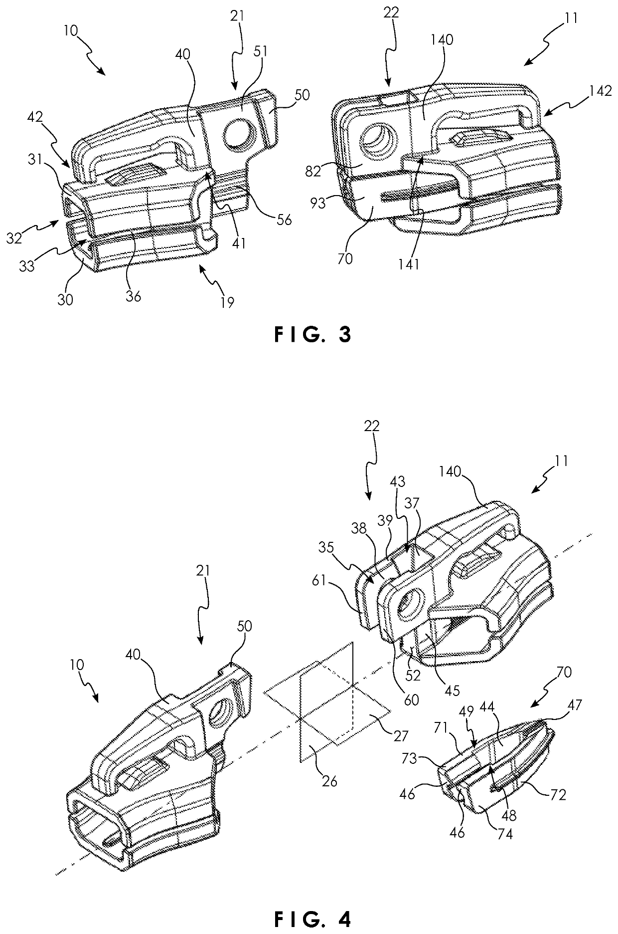
[0039]Front ends of the sliders 10, 11 are arranged opposing one another and have a male part 21 and female part 22 respectively. Rearward ends of the sliders 10, 11 each comprise a body 19 of like form that is tapered in the longitudinal direction and encloses a main ...
second embodiment
[0048]With reference to FIGS. 11 to 13, the zip fastener 220 of the invention comprises a slider 11 (of like form as in the zip fastener 20 and so it is identified with the same reference number) with one of the male and female parts 21, 22 and wherein, essentially, the other of the male and female parts 21, 22, previously disposed on second slider, is instead formed on a fixture 58 fixed at a longitudinal end of the stringers. The male coupler 21 thus likewise opposes the female coupler 22, so zip fastener 220 can be held closed in manner corresponding to that of zip fastener 20. The fixture 58 may include a flange 59 transverse to the male coupling part 21, with holes 62 for receiving a fastener for mounting the fixture 58. A hole 56 adapted to receive a shackle may also be formed on the fixture 58.
third embodiment
[0049]FIG. 14 illustrates the zip fastener 320 of the invention, which differs from the previously described embodiments in respect of the slider 311 on which the female part 22 is disposed, the body 319 of which may be an assembly of inner and outer sections 64, 34 each including a respective one of the inner and outer walls 30, 31. The inner and outer sections 64, 34 may each be one-part components and the web 45 may be integral with the outer section 34. Dividing the slider in this manner either side of the longitudinal-transverse plane 27, or parallel thereto, allows for servicing of the zip fastener while it is assembled on a bag. A screw 65 received in a transverse opening in the web 45 may connect the inner and outer sections 64, 34.
PUM
Abstract
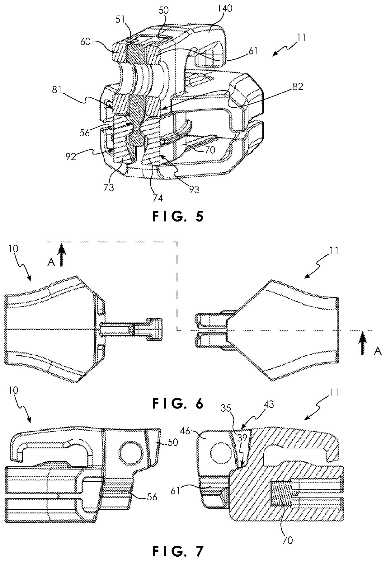
A zip fastener may include a first slider disposed to slide lengthwise along a pair of stringers, and which includes one of a male part and a complementary female part. The other of the male part and the female part is formed on either a member, which may be a fixture fixed to the stringers, or a second slider. The male coupling part includes a neck adjacent an enlarged head, and the female coupling part includes a transverse slot with broad and narrow sections. In a two-handed operation, the male and female parts are mutually engaged to connect the first slider and the member by relative transverse movement, to pass the male part through a mouth of the transverse slot. When latched is closed in this way, axial separation of the first slider from the member is precluded.
Description
TECHNICAL FIELD[0001]The present invention relates to zip fasteners with security features for latching the zip fastener closed.BACKGROUND OF THE INVENTION[0002]Zip fasteners are often used in applications where a degree of security is desirable. Locking the zip fastener closed can be achieved, for instance, by latching a slider to a fixture at one end of the zip or, where the zip includes two sliders, by latching the two sliders together.[0003]While a lock, such as a padlock, can be used to lock the zip fastener closed, this may not be convenient or necessary in all circumstances, so it is advantageous to provide a zip with child-proofing, or a degree of security that is sufficient to defeat casual theft. In particular, this may include an arrangement that is difficult to open with a single hand. CN103653566A describes such a zip fastener with two sliders each having a like locking pull tab, and in which the pull tabs can be interlocked with one another by a slide-and-turn action t...
Claims
Application Information
Patent Timeline
Application Date:The date an application was filed.
Publication Date:The date a patent or application was officially published.
First Publication Date:The earliest publication date of a patent with the same application number.
Issue Date:Publication date of the patent grant document.
PCT Entry Date:The Entry date of PCT National Phase.
Estimated Expiry Date:The statutory expiry date of a patent right according to the Patent Law, and it is the longest term of protection that the patent right can achieve without the termination of the patent right due to other reasons(Term extension factor has been taken into account ).
Invalid Date:Actual expiry date is based on effective date or publication date of legal transaction data of invalid patent.

