Mechanical seal support system

Active Publication Date: 2018-08-02
AES ENG
View PDF26 Cites 0 Cited by
  • Summary
  • Abstract
  • Description
  • Claims
  • Application Information

AI Technical Summary

Benefits of technology

[0037]Preferably, there are no windowed orifices in the system of the invention, which allow t

Problems solved by technology

It has been found that it is difficult to ensure the vessel of a seal support system, and therefore the mechanical seal remains sterile during use.
Hence, the barrier fluid is at risk of becoming stagnant within the vessel and/or contaminated and this m

Method used


Image

  • Mechanical seal support system
  • Mechanical seal support system
  • Mechanical seal support system

Examples


Example

[0051]FIG. 4 is a cross-sectional view of the third embodiment of the system of invention described in FIG. 1 and FIG. 2, whereby a convoluted element 31 is situated in the internal cavity formed by the two sections of vessel 1, being section 15 and section 16, and connected to two orifices 32 and 33, such that fluid may be passed through either of the aforementioned orifices and pass out of the opposing orifice without coming into contact with any of the barrier fluid contactable surfaces of the vessel 1.

Example

[0052]FIG. 5 is a cross-sectional view of the fourth embodiment of the system of invention described in FIG. 1, FIG. 2, FIG. 3 and FIG. 4, whereby both the cleaning ball 29 and the convoluted coil 31 are included in the same embodiment of the system.

Example

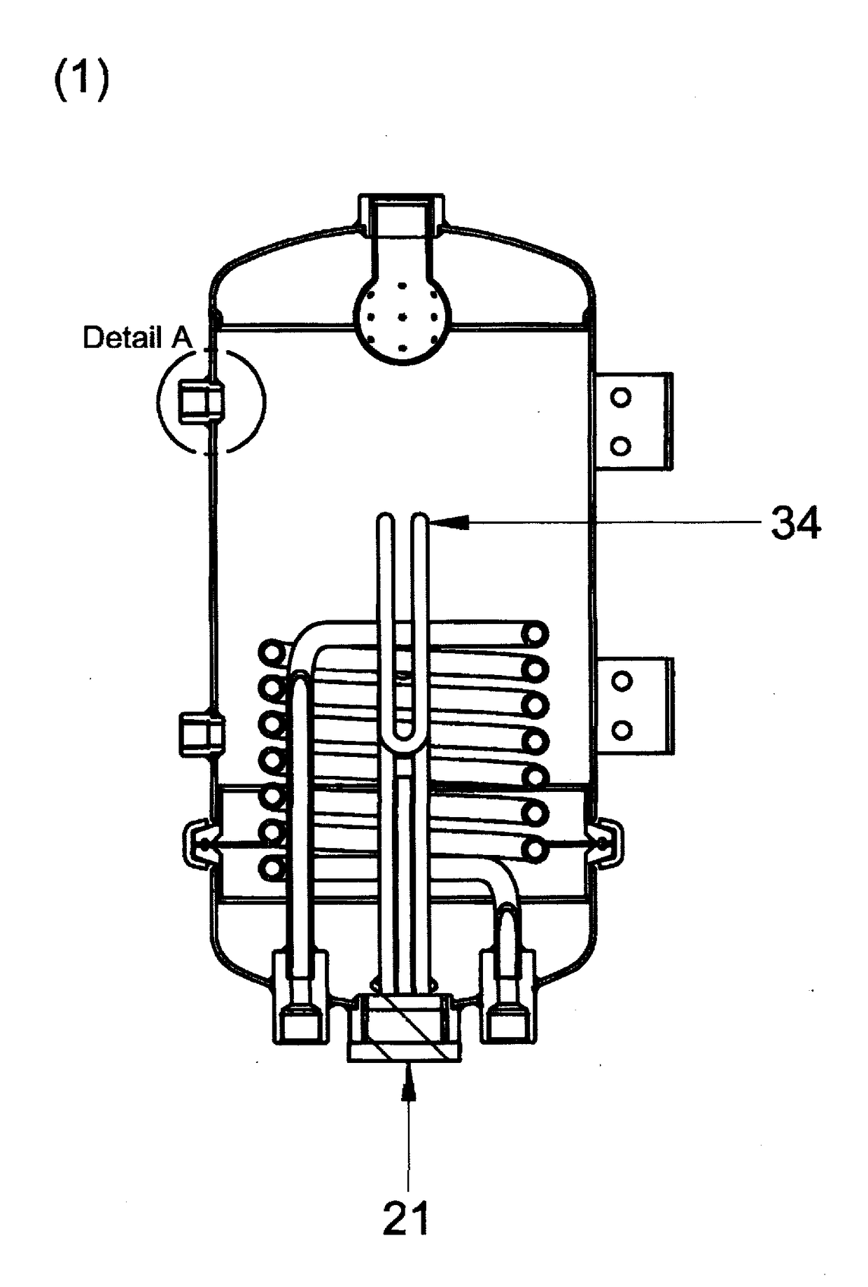
[0053]FIG. 6 is a cross-sectional view of the fifth embodiment of the system of invention described in FIG. 1, FIG. 2, FIG. 3, FIG. 4 and FIG. 5, whereby the system of invention detailed in FIG. 5, and all subsequent figures, also encapsulates a secondary convoluted metallic element 34. Preferably, the secondary convoluted metallic element 34 is communicated to through orifice 21 by an external power supply such that, as and when required, the vessel 1 and all fluid in contact with the barrier contactable surfaces may be heated to a defined temperature and held for a defined amount of time.

[0054]Preferably, the secondary convoluted metallic element 34 may be set to automatically raise the temperature of the fluid within the system to a predefined temperature and hold it for a predefined amount of time.

[0055]FIG. 7 is a detail view of a welded coupling present on all embodiments of the invention whereby it is shown that for the coupling 35 there is an exterior weld 36, present on the...


PUM


Abstract

A mechanical seal support system for a sealing device for sealing a piece of industrial equipment, includes a mechanical seal for sealing the piece of industrial equipment and a system vessel for containing barrier fluid for the mechanical seal and being circumferentially split into a plurality of sections detachably attached for retaining pressure. The system vessel includes a clean-in-place (CIP) assembly, a cooling element and device for sterilizing the system vessel. The device for sterilizing the a heating element is formed as a coiled tubular element for the barrier fluid to pass therethrough, with closed-loop pipe work included for connecting the system vessel to the mechanical seal and a drain and filling device for removing and adding the barrier fluid to the system vessel.

Description

CROSS-REFERENCE TO RELATED APPLICATIONS[0001]This is a continuation-in-part of U.S. patent application Ser. No. 14 / 889,920, filed Nov. 9, 2015, which represents the U.S. National Phase patent application, pursuant to 35 U.S.C. § 371, of P.C.T. International Patent Application No. PCT / GB2014 / 000182, filed May 9, 2014.BACKGROUND OF THE INVENTIONTechnical Field of the Invention[0002]The present invention relates, generally, to mechanical seal support systems and, more particularly, to mechanical seal support systems, which are used with mechanical seals for the containment of process fluid.Description of the Prior Art[0003]A seal support system typically comprises of a vessel or tank, which generally contains a volume of fluid. The vessel is piped to a sealing device on a pump, mixer or item of rotating equipment. Generally a return pipe is lead back to the vessel from the sealing device, hence closing the “loop.” This allows the fluid, contained in the vessel, to enter and exit the se...

Claims


Application Information

Patent Timeline
IPC IPC(8): F16J15/34
CPCF16J15/3464F16J15/3404Y10T137/6416
Inventor STEPHENSON, HEATH
Owner AES ENG
Why Eureka
Try Eureka