Vehicle seat with side airbag device

a technology of side airbags and vehicle seats, which is applied in the direction of vehicle components, pedestrian/occupant safety arrangements, vehicle arrangements, etc., can solve the problem of difficult to apply the reaction force from the vehicle cabin side portion to the side airbag,

Active Publication Date: 2018-08-09
TOYOTA JIDOSHA KK
View PDF6 Cites 18 Cited by
  • Summary
  • Abstract
  • Description
  • Claims
  • Application Information

AI Technical Summary

Benefits of technology

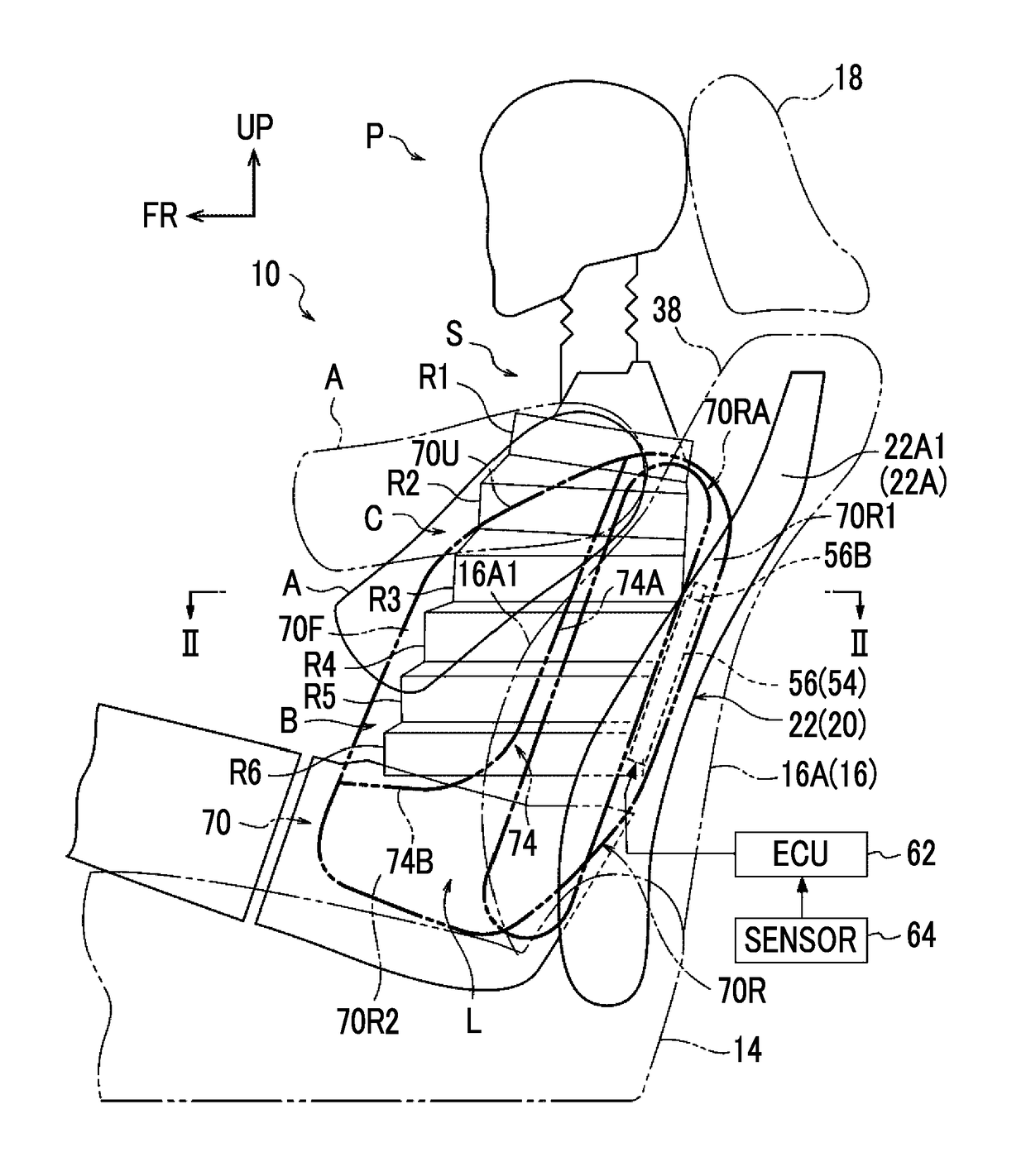
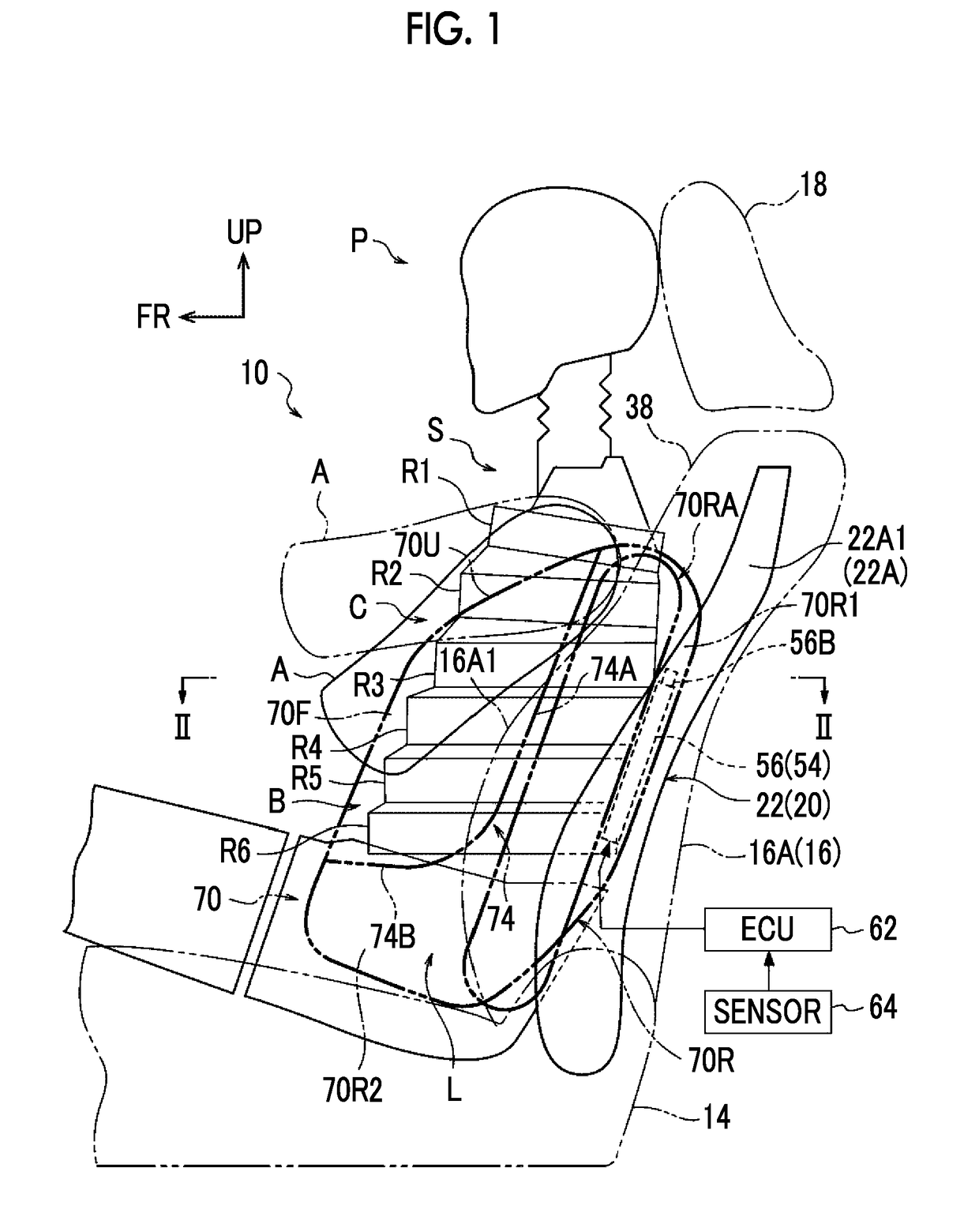
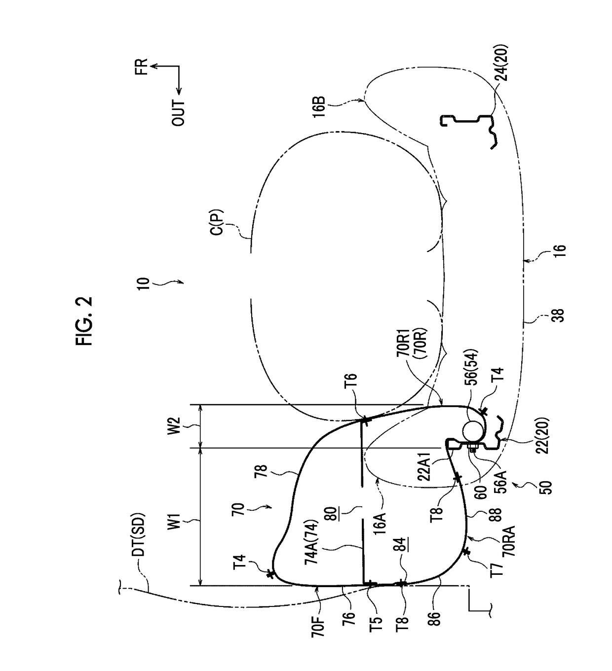
[0005]However, in the vehicle seat having the above configuration, since the gas generating device attached to the inside of the outer side frame in the vehicle cabin (inside in a vehicle-width direction) introduces the gas substantially in the forward direction in the side airbag, the side airbag easily inflates and deploys toward a vehicle front side and the inside in the vehicle-width direction and is less likely to inflate and deploy toward the outside in the vehicle-width direction (toward a vehicle cabin side portion). Therefore, it is difficult for the reaction force from the vehicle cabin side portion to be applied to the side airbag until the vehicle cabin side portion intrudes toward the inside in the vehicle-width direction due to a collision load of the side collision. As a result, the occupant restraining force of the side airbag at an initial stage of restraining the occupant by the side airbag temporarily decreases. Therefore, there is room for improvement from the viewpoint of further improving the initial occupant restraint performance of the side airbag.
[0037]As described above, with the vehicle seat with a side airbag device according to the aspect, the initial occupant restraint performance of the side airbag in the configuration in which the gas generating device is attached to the inside of the outer side frame in the seat back in the vehicle-width direction can be further improved.

Problems solved by technology

Therefore, it is difficult for the reaction force from the vehicle cabin side portion to be applied to the side airbag until the vehicle cabin side portion intrudes toward the inside in the vehicle-width direction due to a collision load of the side collision.

Method used


Image

  • Vehicle seat with side airbag device
  • Vehicle seat with side airbag device
  • Vehicle seat with side airbag device

Examples


second embodiment

[0130]FIG. 9 is a plan sectional view illustrating the inflated and deployed state of the side airbag 70 in the vehicle seat 100 provided with a side airbag device according to a second embodiment. The second embodiment has basically the same configuration as the first embodiment, but an additional chamber 70RB provided in the side airbag 70 is different from the additional chamber 70RA according to the first embodiment.

[0131]As illustrated in FIGS. 9 and 11 to 13, the additional chamber 70RB has a pair of right base cloth 104 and left base cloth 102 arranged in the right-left direction (thickness direction; width direction) of the side airbag 70. The right base cloth 104 and the left base cloth 102 are formed of the same cloth material as the outer base cloth 76 and the like and are formed in a substantially long rectangular shape having the up-down direction of the side airbag 70 as their longitudinal direction. The outer peripheral portions of the base cloth 104, 102 are sewn to ...

third embodiment

[0137]FIG. 14 is a plan sectional view illustrating the inflated and deployed state of the side airbag 70 in a vehicle seat 120 provided with a side airbag device according to a third embodiment. In the side airbag 70 according to the third embodiment, the additional chamber 70RA and the gas introduction port 84 according to the first embodiment are not provided. Instead, in the third embodiment, the side airbag 70 is attached to the outer side frame 22 in a different manner from that of the first embodiment (see FIGS. 14 and 15). Accordingly, the inflation width of the side airbag 70 in the vehicle-width direction is set to be greater outside the outer side surface 22A1 of the outer side frame 22 in the vehicle-width direction than inside the outer side surface 22A1 in the vehicle-width direction. This will be described in detail below.

[0138]As in the first embodiment, the side airbag 70 according to the embodiment includes the outer base cloth 76 and the inner base cloth 78. The o...

fourth embodiment

[0144]FIG. 17 is a side view of an inflated and deployed state of a side airbag 132 in a vehicle seat 130 provided with a side airbag device according to a fourth embodiment. In the fourth embodiment, the configuration of the side airbag 132 is different from that of the side airbag 70 according to the first embodiment. The side airbag 132 includes a front base cloth 134 and a rear base cloth 136 arranged in the vehicle front-rear direction in the inflated and deployed state. The front base cloth 134 and the rear base cloth 136 are formed by cutting the same cloth material as the outer base cloth 76 according to the first embodiment and the like into a long rectangular shape. The front base cloth 134 and the rear base cloth 136 are formed to have the same size and shape. As the base cloth 134, 136 are sewn to each other at sewn portions T11, T12 illustrated in FIG. 18 and sewn portions (not illustrated), the side airbag 132 is formed in an elongated bag shape.

[0145]In the rear porti...


PUM


Abstract

A vehicle seat with a side airbag device includes: a gas generating device attached to an inner side of an outer side frame in a vehicle-width direction, which is disposed in a side portion on an outside of a seat back in the vehicle-width direction; a side airbag which inflates and deploys to expand over the outer side frame from a vehicle front side of the outer side frame in the vehicle-width direction by receiving gas from the gas generating device accommodated in the side airbag; and an inflation width expansion portion which is provided in the side airbag and causes an inflation width of the side airbag in the vehicle-width direction to be greater outside a side surface provided on an outside of the outer side frame in the vehicle-width direction than inside the side surface.

Description

INCORPORATION BY REFERENCE[0001]The disclosure of Japanese Patent Application No. 2017-018647 filed on Feb. 3, 2017 including the specification, drawings and abstract is incorporated herein by reference in its entirety.BACKGROUND1. Technical Field[0002]The present disclosure relates to a vehicle seat with a side airbag device.2. Description of Related Art[0003]In a vehicle seat described in Japanese Unexamined Patent Application Publication No. 2006-513083 (JP 2006-513083 A), an airbag unit (side airbag module) is disposed inward of a beam (outer side frame) included in the frame of a seat back in a vehicle cabin. In the side airbag module, an inflator (gas generating device) disposed in the rearmost region of the outer side frame introduces gas substantially in a forward direction in an airbag (side airbag) during a side collision of the vehicle. Accordingly, at least a portion of the side airbag is caused to widen (inflate and deploy) between the outer side frame and a seated occu...

Claims


Application Information

Patent Timeline
Patent Type & Authority Applications(United States)
IPC IPC(8): B60R21/231B60R21/26B60R21/207B60R21/233
CPCB60R21/23138B60R21/26B60R21/207B60R21/233B60R2021/23146B60R2021/23509B60R2021/23382B60R21/237B60N2/42B60R21/231B60R21/2338B60R2021/23386B60R21/264B60R21/2334B60R21/2346B60R2021/26023B60R21/00
Inventor FUKAWATASE, OSAMUKOMURA, TAKAMICHIKUNISADA, MASATONAGURA, HIROYUKIKAWAI, TAKUMASHIMIZU, TAKAYUKI
Owner TOYOTA JIDOSHA KK
Why Eureka
Try Eureka