Valve for pressurized environments

Active Publication Date: 2018-08-09
SCHREDER SA
View PDF12 Cites 0 Cited by
  • Summary
  • Abstract
  • Description
  • Claims
  • Application Information

AI Technical Summary

Benefits of technology

[0019]In the case of charging valves, pin overshooting is better controlled (the chain of dimensions is not as long) and the risk that the spindle will escape the tappet of the connector is reduced (continuous radial guidance of the spindle head by

Problems solved by technology

This has the major disadvantage of complicating assembly

Method used


Image

  • Valve for pressurized environments
  • Valve for pressurized environments
  • Valve for pressurized environments

Examples


Example

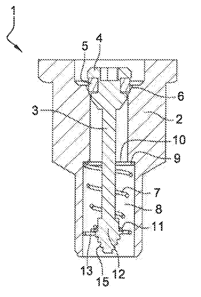
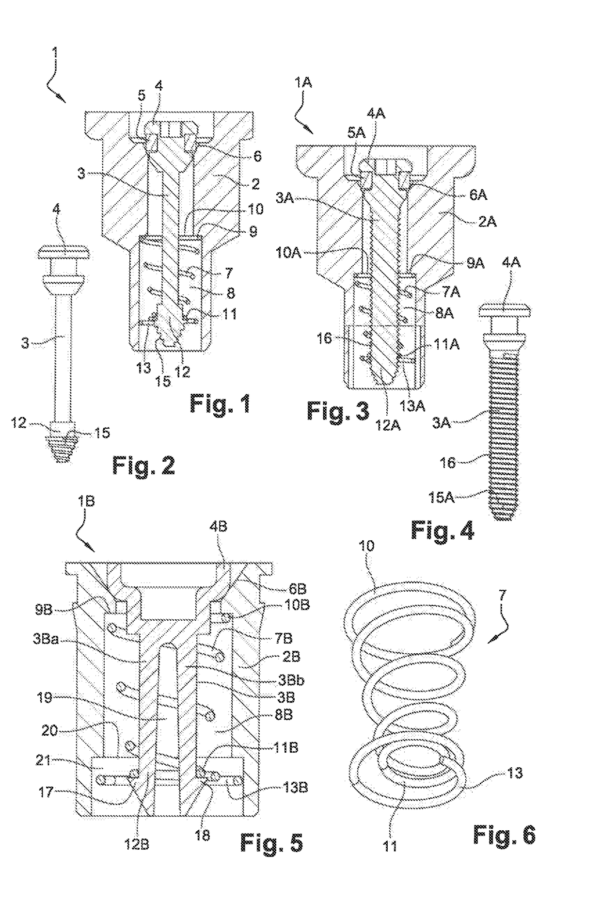
[0035]The valve 1 designated overall in FIG. 1 includes a tubular body 2 wherein a valve stem 3 is able to move axially, the head 4 whereof is provided or not with a sealing lining 5 and suitable for cooperating, in a sealed manner, with a corresponding seat 6 of the valve body 2, the stem 3 acting depending on a predetermined pressure, against a coiled spring 7, 7A, 7B for example with a partially conical shape 7 housed in a chamber 8 of a circular section, coaxial with the tubular body 2 and disposed between a bearing zone 9 with respect to it and the stem 3, to return the latter toward the seat 6 with a predetermined force.

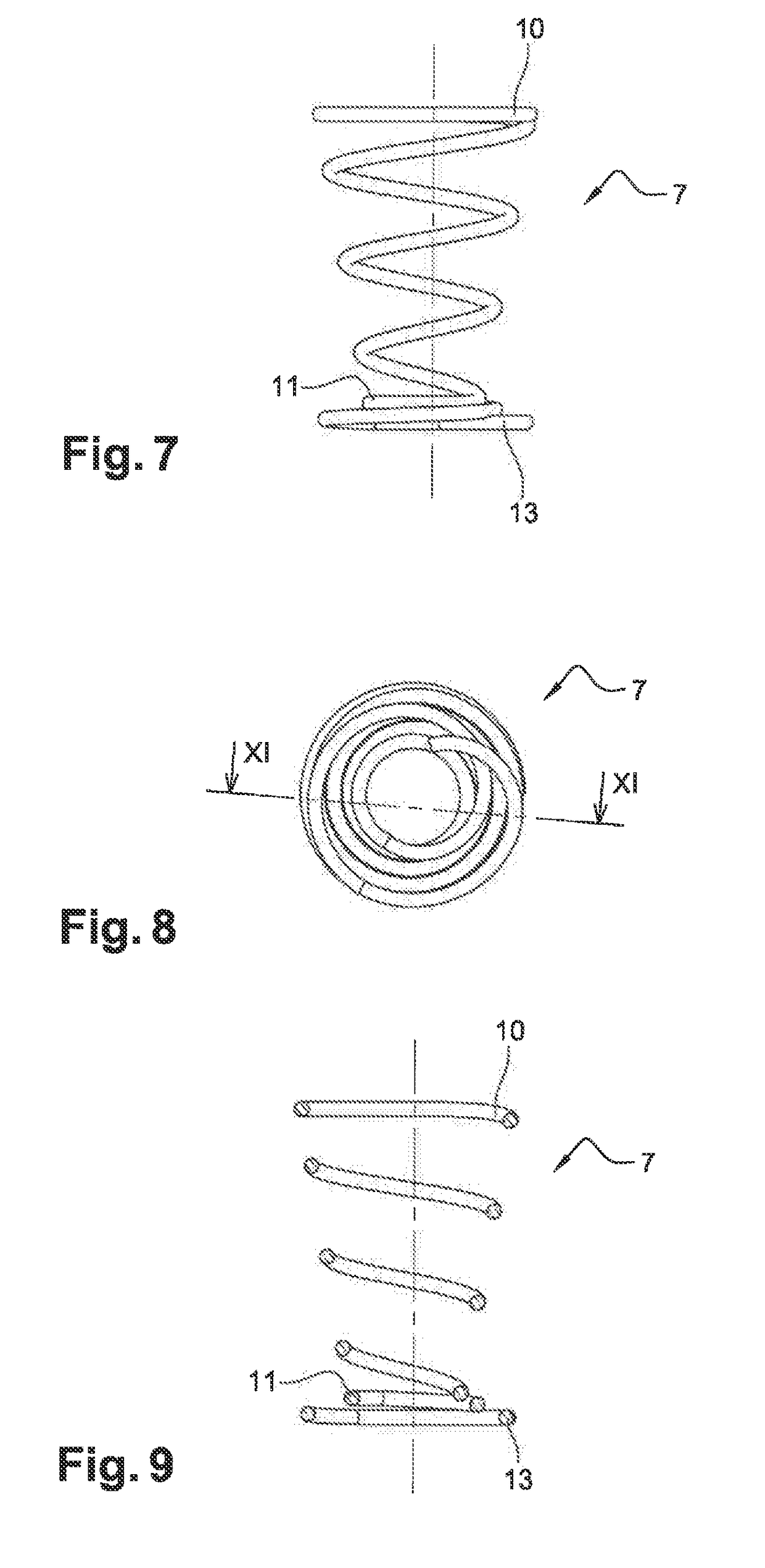
[0036]According to one implementation of the invention, the return spring 7, 7A, 7B has a tapered cylindrical shape, of which the turn constituting its large base 10, 10A, 10B is designed to bear on the bearing zone 9, 9A, 9B of the chamber 8, 8A, 8B of the body 2, 2A, 2B of the valve 1, while the turn 11, 11A, 11B constituting its small end is connected with t...


PUM


Abstract

The invention relates to a valve comprising a tubular body in which a valve stem moves axially, the head of the stem cooperating with a corresponding seat on the valve body, said stem acting against a coiled spring that is housed in a chamber of circular cross-section and disposed between a bearing zone at a first end of the chamber and the stem in order to return the stem to the seat, said spring comprising: a first end with a large turn of a diameter substantially identical to a diameter of the chamber at the first end; and a second end with a small turn connected to the shank or the head of the stem and a second large turn for centering and radial stabilization in the chamber.

Description

RELATED APPLICATIONS[0001]The present application is a National Phase entry of PCT Application No. PCT / FR2016 / 050734, filed Mar. 31, 2016, which claims priority to FR 1553945, filed Apr. 30, 2015, the contents of each being incorporated herein by reference in their entireties.TECHNICAL FIELD[0002]The present invention relates to a valve subjected to pressurized environments, and the like, such as a charging valve, a check valve, an overpressure valve or a pressure regulator.BACKGROUND ART[0003]Known valves of this type include a tubular body in which a valve stem moves axially, the head whereof is provided or not with a sealing lining suitable for cooperating, in a sealed manner, with a corresponding seat of the valve body, the stem acting depending on a predetermined pressure, against a coiled spring housed in a chamber coaxial with the tubular body and disposed between a bearing zone with respect to it and the stem, to return the latter to the seat with a predetermined force.[0004...

Claims


Application Information

Patent Timeline
IPC IPC(8): F16K15/06F16K1/02F16K1/20
CPCF16K15/063F16K1/02F16K1/2071F16K31/566F16F1/025F16F1/08F16K17/06Y10T137/7936
Inventor GRESSET, BENOITROBERT, SEBASTIEN
Owner SCHREDER SA
Why Eureka
Try Eureka