Molding apparatus and gas compression molding process

Inactive Publication Date: 2011-11-17
ICHIA TECH
View PDF0 Cites 1 Cited by
  • Summary
  • Abstract
  • Description
  • Claims
  • Application Information

AI Technical Summary

Benefits of technology

[0011]Compared with conventional techniques, in the present invention, a molding apparatus has a multiple mold cavities for production by multiple plates and multiple mold cavities, which results in a pluralit

Problems solved by technology

However, in such process, the metal plate tends to be damaged at the bending of the housing profile.
However, since the stripping is carried out by

Method used


Image

  • Molding apparatus and gas compression molding process
  • Molding apparatus and gas compression molding process
  • Molding apparatus and gas compression molding process

Examples


Embodiment Construction

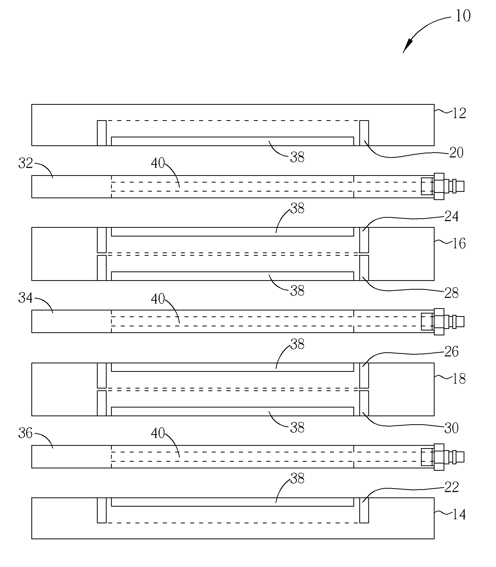
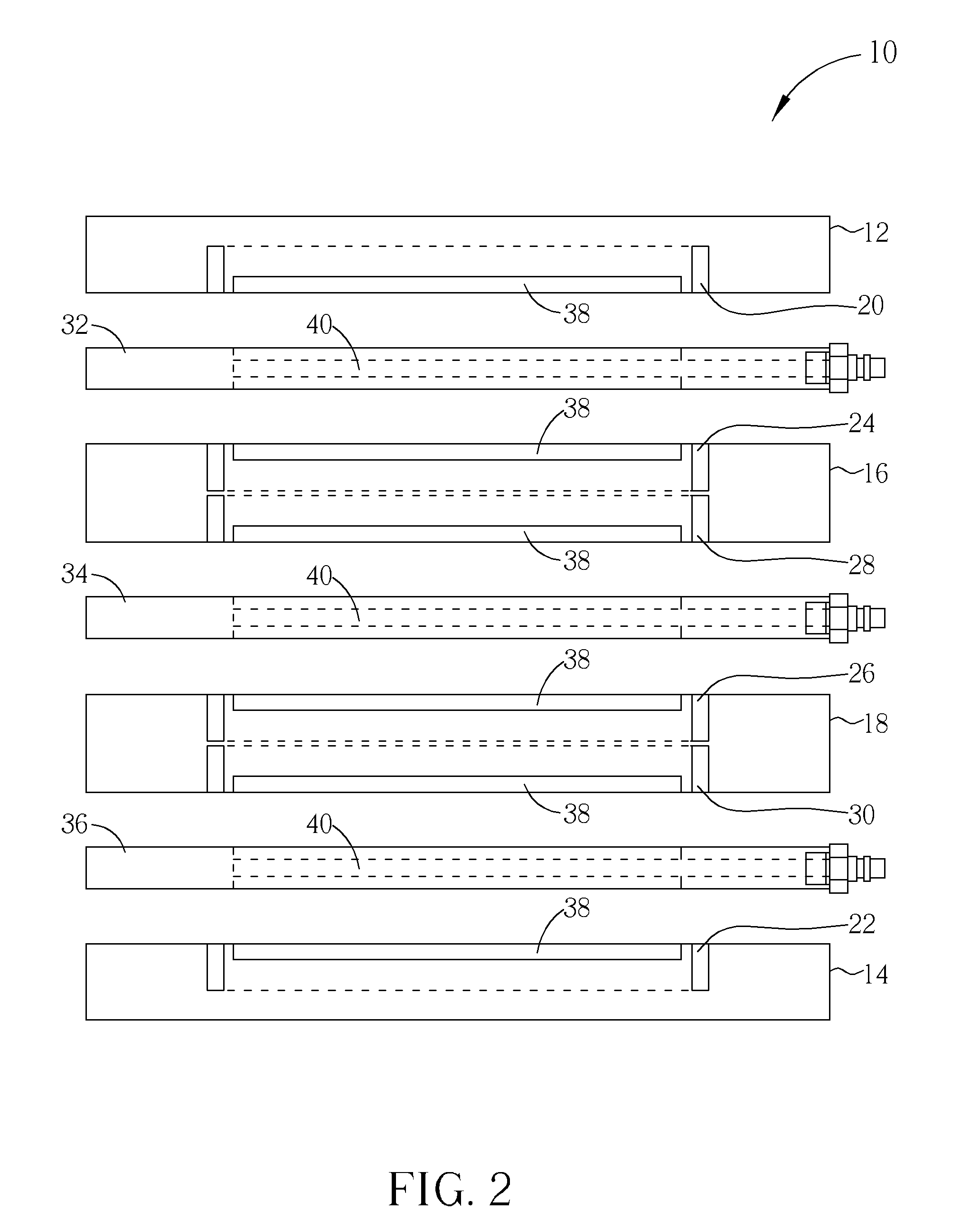
[0023]FIG. 2 is a schematic cross-sectional view of a molding apparatus for illustrating the present invention. The molding apparatus 10 includes molding dies 12, 14, 16 and 18, strippers 20 and 22 respectively disposed in recesses of the molding dies 12 and 14, strippers 24 and 26 respectively disposed in recesses of the molding dies 16 and 18 at one face, strippers 28 and 30 respectively disposed in recesses of the molding dies 16 and 18 at another face, sealing dies 32, 34 and 36 respectively disposed between the molding die 12 and the molding die 16, between the molding die 16 and the molding die 18, and between the molding die 18 and the molding die 14.

[0024]The molding dies 12 and 14 may each include a die cavity 38 at one face (or referred to as “side”), and the molding dies 16 and 18 may each include two die cavities 38 at two faces. The cavity per se or a die core when which is further included may have a shape as a desired shape for the working article to be shaped into, n...


PUM

PropertyMeasurementUnit
Temperatureaaaaaaaaaa
Distanceaaaaaaaaaa

Abstract

A molding apparatus has a multilayered structure with multiple die cavities, in which, one or a plurality of constraining components are each employed to pull both a stripper in a molding die and an adjacent sealing die by two ends, so as to strip the molded article and confine a distance between the two dies. Furthermore, during a molding process, a plurality of plates are each disposed between two dies. The molding apparatus is allowed to be closed gradually. After the molding, the molding apparatus is allowed to be opened gradually. When the stripper within the molding die and the sealing die both moved to be held by the two ends of the constraining components respectively, the stripper in each molding die will be pulled out by the buckle ring, thereby to strip the molded articles. Accordingly, a plurality of molded articles can be obtained in one molding operation.

Description

BACKGROUND OF THE INVENTION[0001]1. Field of the Invention[0002]The present invention relates to a molding process and apparatus, and particularly to a gas-compression molding process and apparatus.[0003]2. Description of the Prior Art[0004]Most metal housings of electronic products are conventionally manufactured by punch press. However, in such process, the metal plate tends to be damaged at the bending of the housing profile. Air compression formation is thus developed. For example, as shown in FIG. 1, a magnesium alloy plate 1 is placed between a molding die 3 and a sealing die 4 of a die 2 and the die 2 is closed to form a cavity 5. The molding die 3 has a molding die cavity 6. A compressed air from an air compressor 8 is injected into a cavity 5 to press the magnesium alloy plate 1 forward to the molding die cavity 6 to attach the wall of the molding die 3 to form into a shape.[0005]In Japan Patent Application Publication No. 2004-249320, a method of air compression to make ma...

Claims


Application Information

Patent Timeline
IPC IPC(8): B29C51/10
CPCB21D26/031B29C51/30B29C51/10B21D45/04B21D26/025B21D35/003B29C2791/007
Inventor HSU, PO-NANLIU, KUN-SHENGWU, CHE-TUNGYANG, JUI-HUNG
Owner ICHIA TECH
Why Eureka
Try Eureka