[0009]It is thus an aim of the present invention to provide a thrust return pedal in which the thrust applied to the pedal is immediate and well controlled. Advantageously, the occurrence of a hard point will be immediate when the conditions for establishing this hard point have been produced. Preferably, this pedal will additionally make it possible to vary the point of application of the hard point and also the amplitude of this hard point. In one embodiment, it will be advantageous for an alert message, in the form, for example, of a vibration of the pedal, to be able to be transmitted to the driver.
[0012]In this new design, the
electric motor does not just carry out an adjustment allowing the stiffness of a control member to be adjusted but also exerts a force transmitted directly, or by the intermediary of a reduction, to this control member. This allows better control of the action applied to this control member. The thrust return pedal according to the invention thus makes it possible to have a hard point present at a predetermined (fixed or variable) position of the travel of the control device and not a hard point which is established when the control device reaches a predetermined position. With a device according to the invention, it is possible for each position of the control member to be assigned a force, which is variable over time, to be applied to this member to keep it in this position according to a predetermined law that can vary over time. The variation of this force to be applied is obtained by managing the value of the current feeding the electric motor. In this way, the amplitude of the hard point may be adapted by the motor which acts on the control device.
[0013]In a preferred embodiment, the unidirectional connection has a flexibility which makes it possible, according to the relative position of the control device and of the thrust return mechanism, to depress the control member as far as the hard point without transmitting thrust to the thrust return mechanism. Because of this flexibility, the control device and the thrust return mechanism may work independently of one another as long as the connection is free, that is to say where no thrust is transmitted from the thrust return mechanism to the control device (or vice versa). By contrast, when the connection is blocked, the user who depresses the control member does so against the force supplied by the electric motor of the thrust return mechanism or else this mechanism acts to raise the control member.
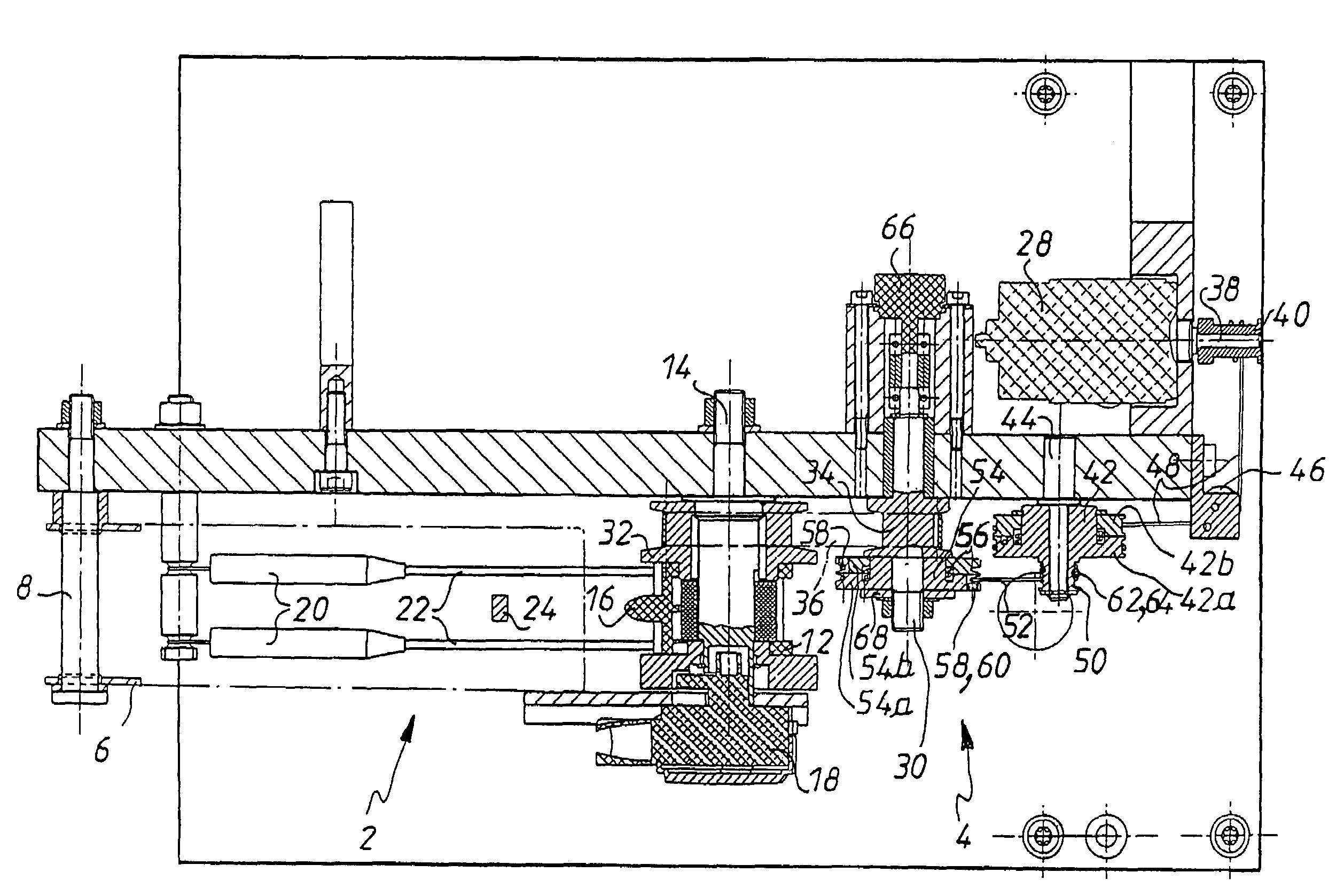
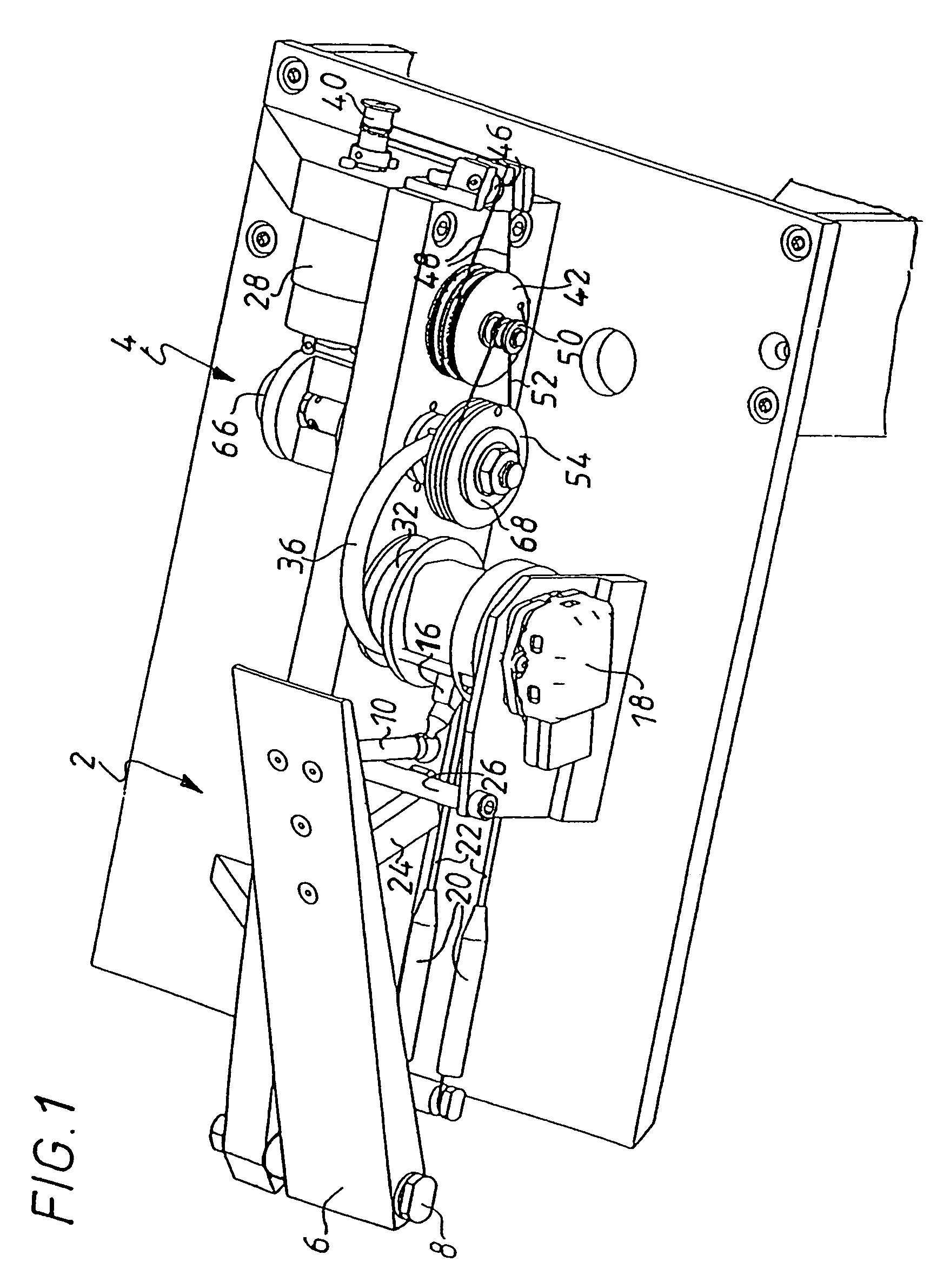
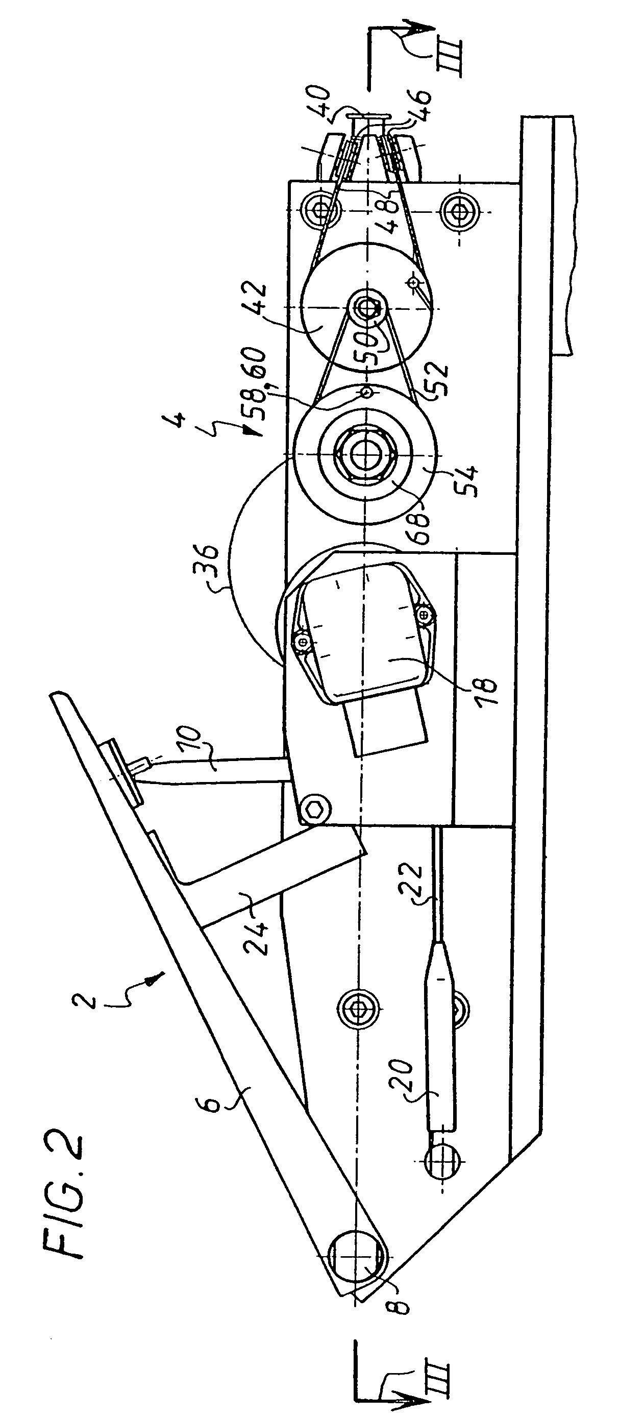
[0014]To make it possible to have a hard point whose position is variable during the depression of the control member, the electric motor advantageously allows adjustment of the position of a connection member and the unidirectional connection means are arranged between this connection member and the control device. In this embodiment, the connection member is, for example, a spindle whose angular position is adjusted by the electric motor.
[0016]A cable-type reduction is preferably provided between the electric motor and the connection member. In this way, when the unidirectional connection is engaged, the forces transmitted by a user on the control device are retransmitted to the motor with a lesser torque. Tests also demonstrated that this reduction made it possible to reduce the unwanted variations in the torque of the electric motor which are transmitted to the control member, this being more pleasant for the user.

