Elliptical ultrasonic machining device powered by non-contact induction

a non-contact induction, machining device technology, applied in the direction of manufacturing tools, mechanical vibration separation, metal-working machine components, etc., can solve the problems of limited rotation speed and meet the automatic tool change requirement of the machine tool, and achieve the effect of reducing the rotation radius reducing the rotation inertia thereof, and increasing the rotation stability of the elliptical ultrasonic spindle shank

Active Publication Date: 2018-09-06
BEIHANG UNIV
View PDF0 Cites 19 Cited by
  • Summary
  • Abstract
  • Description
  • Claims
  • Application Information

AI Technical Summary

Benefits of technology

[0035]Firstly, the primary magnetic core seat where the induction power supply primary units are arranged and the secondary magnetic core seat where the induction power supply secondary units are arranged have the same circle center, and the secondary magnetic core seat is located inside the primary magnetic core seat, so that a rotation radius of the elliptical ultrasonic spindle shank is decreased, a rotation inertia thereof is lowered, and a rotation stability of the elliptical ultrasonic spindle shank is increased.

Problems solved by technology

During the rotation process, the mechanical contact point easily generates the spark, and the rotation speed is limited, which is especially unable to meet the automatic tool change requirement of the machine tool.

Method used


Image

  • Elliptical ultrasonic machining device powered by non-contact induction
  • Elliptical ultrasonic machining device powered by non-contact induction
  • Elliptical ultrasonic machining device powered by non-contact induction

Examples


Embodiment Construction

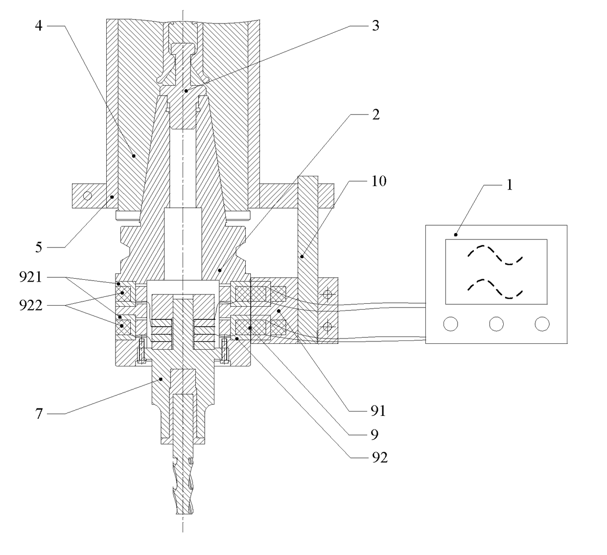
[0043]As shown in FIG. 1, according to a preferred embodiment of the present invention, an elliptical ultrasonic machining device comprises an elliptical ultrasonic power supply 1, an induction power supply device 9, an elliptical ultrasonic spindle shank 2, and a machine tool spindle 4 of a machine tool. The present invention is further described with accompanying drawings as follows.

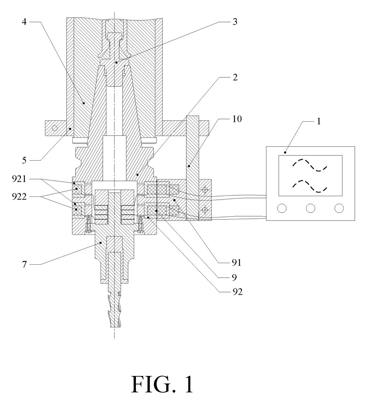
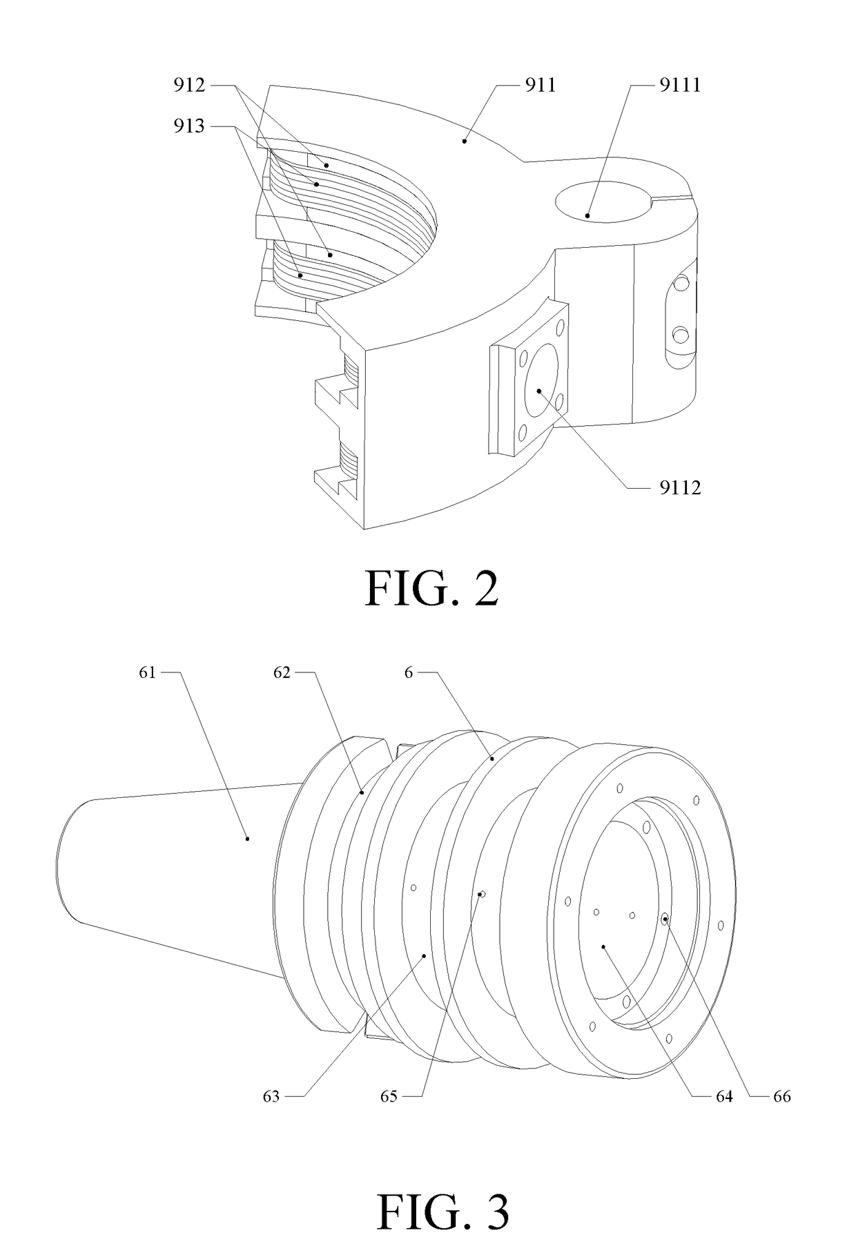
[0044]As shown in FIG. 1, an elliptical ultrasonic machining device powered by non-contact induction mainly comprises an induction power supply device 9 and an elliptical ultrasonic spindle shank 2, wherein: induction power supply secondary units 92 of the induction power supply device 9 are arranged at a BT spindle shank shell 6 of the elliptical ultrasonic spindle shank 2; induction power supply primary units 91 of the induction power supply device 9 are arranged at a primary magnetic core seat 911 outside the elliptical ultrasonic spindle shank 2; the primary magnetic core seat 911 and the elliptica...


PUM

PropertyMeasurementUnit
thicknessaaaaaaaaaa
frequency resolutionaaaaaaaaaa

Abstract

An elliptical ultrasonic machining device powered by non-contact induction mainly includes an induction power supply device and an elliptical ultrasonic spindle shank, wherein: induction power supply secondary units of the induction power supply device encircle a spindle shank shell of the elliptical ultrasonic spindle shank; induction power supply primary units are arranged at a primary magnetic core seat outside the elliptical ultrasonic spindle shank; the primary magnetic core seat and the elliptical ultrasonic spindle shank have a same circle center, and a small gap exists between the primary magnetic core seat and the elliptical ultrasonic spindle shank; the primary magnetic core seat is fastened on a machine tool spindle seat of a machine tool through a support and keeps still; the elliptical ultrasonic spindle shank is mounted on a machine tool spindle through a taper shank and rotates with the spindle in a high speed.

Description

CROSS REFERENCE OF RELATED APPLICATION[0001]The application claims priority under 35 U.S.C. 119(a-d) to CN 201710334183.4, filed May 12, 2017.BACKGROUND OF THE PRESENT INVENTIONField of Invention[0002]The present invention relates to an ultrasonic machining device, and more particularly to an elliptical ultrasonic machining device powered by non-contact induction, belonging to a technical field of ultrasonic machining.Description of Related Arts[0003]Ultrasonic machining technology is a special machining method based on traditional cutting machining combined with vibration of ultrasonic frequency to realize material removal. Compared with the traditional cutting machining, the ultrasonic machining is able to decrease the cutting force, cutting temperature and tool wear, and increase the surface accuracy. Thus, the ultrasonic machining technology is suitable for machining of various difficult-to-machine materials and difficult-to-machine structures, and especially suitable for finish...

Claims


Application Information

Patent Timeline
Patent Type & Authority Applications(United States)
IPC IPC(8): B23C5/16B06B1/06B23C5/10B23C9/00
CPCB23C5/16B06B1/06B23C5/10B23C9/005B23C2270/10B23Q2230/004B23C9/00B06B3/00B23B37/00B23C5/26B23B2260/108B23B2270/10B23Q1/0027
Inventor JIANG, XINGGANGZHANG, DEYUAN
Owner BEIHANG UNIV
Why Eureka
Try Eureka