
In-vehicle device

a technology for vehicles and parking lots, applied in vehicle parts, instruments, steering parts, etc., can solve the problems of hindering the exiting vehicle from the number of vehicles that can be parked relative to an area of the parking lot has not changed much, etc., and achieves efficient parking and smooth exiting the parking lot

Active Publication Date: 2018-09-13
DENSO TEN LTD
View PDF2 Cites 10 Cited by
  • Summary
  • Abstract
  • Description
  • Claims
  • Application Information

AI Technical Summary

Benefits of technology

The patent text describes a technology that helps vehicles smoothly exit parking lots, even when there are many other vehicles being efficiently placed. The technical effect of this technology is to improve the overall efficiency of parking lots and to make it easier for vehicles to leave them.

Problems solved by technology

However, in this parking management system, since the traveling road is provided in front of each parking position (each parking frame), a number of vehicles that can be parked relative to an area of the parking lot has not changed much compared to before.
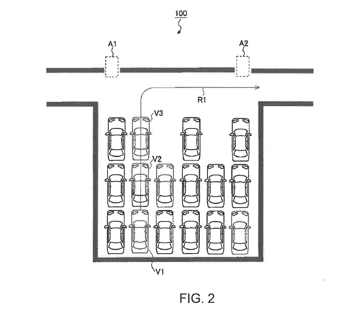
Here, when attempting an efficient parking to increase the number of vehicles that can be parked, relative to the area of the parking lot, without being limited by a concept of the parking frame, there is a possibility that the other vehicles may exist on the traveling route of the exiting vehicle and become obstacles that hinder the exiting vehicle from exiting the parking lot.

Method used


Image

  • In-vehicle device
  • In-vehicle device
  • In-vehicle device

Examples


modification example

[0057]The above embodiment is merely an illustrative example in all respects and should be considered to be nonrestrictive, and the technological scope of the invention is indicated not by the description of the above embodiment but rather by the scope of the claims, and it should be understood to include all modifications with an equivalent meaning to and within the scope the claims.

[0058]For example, in the above-described embodiment, the in-vehicle device requests the other vehicles to move using the vehicle-to-vehicle communication, but the parking management apparatus 20 may instruct the other vehicles to move. In this case, as illustrated in FIG. 5, in a case where the parking management apparatus 20 receives the exit request signal from the user terminal 10, the parking management apparatus 20 transmits the exit instruction to the in-vehicle device that is mounted on the vehicle requested to exit the parking lot (a step S201). The parking management apparatus 20 determines wh...


PUM


Abstract

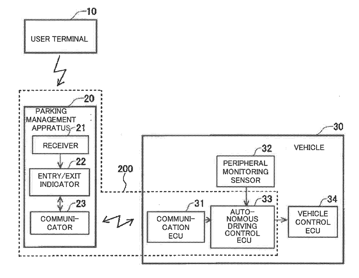
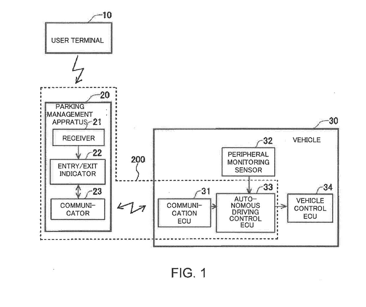
An in-vehicle device that is mounted on a host vehicle, the in-vehicle device includes a receiver, and an electronic control unit. The receiver receives an exit instruction. The electronic control unit (a) determines whether or not other vehicles exist on an exit travel route from a current parking position of the host vehicle to a getting-on area when the exit instruction has been received by the receiver, and (b) requests the other vehicles existing on the exit travel route to move out of the exit travel route using vehicle-to-vehicle communication in a case where the electronic control unit determines that the other vehicles exist on the exit travel route.

Description

BACKGROUND OF THE INVENTIONField of the Invention[0001]The invention relates to a technology that controls exiting of a vehicle in a valet parking lot.Description of the Background Art[0002]Parking lots are mainly divided into two types of parking lots. One type is a self-parking lot and the other type is a valet parking lot.[0003]The self-parking lot is a parking lot in which a vehicle is moved to a parking position by user's driving of the vehicle when entering the parking lot and the vehicle is moved from the parking position by the user's driving of the vehicle when exiting the parking lot. Therefore, in the self-parking lot, the user of the vehicle gets on or off the vehicle in the parking position.[0004]The valet parking lot is a parking lot in which the vehicle is moved from a getting-off area to the parking position by a method other than the user's driving of the vehicle after the user of the vehicle gets off the vehicle in the getting-off area when entering the parking lot...

Claims


Application Information

Patent Timeline
Patent Type & Authority Applications(United States)
IPC IPC(8): G08G1/14
CPCG08G1/144G08G1/146B62D15/0285
Inventor TSUYUNASHI, MASASHI
Owner DENSO TEN LTD
Learn More