System for implanting in bone tissue

a bone tissue and implantable technology, applied in the field of bone tissue implantable device system, can solve the problems of limited clinical outcomes so far, and achieve the effect of improving the implantation of implantable device and accurate placement of pedicle screws

Active Publication Date: 2018-10-04
KONINKLJIJKE PHILIPS NV
View PDF5 Cites 3 Cited by
  • Summary
  • Abstract
  • Description
  • Claims
  • Application Information

AI Technical Summary

Benefits of technology

The present invention aims to improve the accuracy and reliability of implanting devices in bone tissue, particularly in the spine. The invention provides a detection system that can accurately place a screw and sense the surrounding tissue, preventing damage to vital structures and ensuring proper placement. The system can also measure the hardness of the bone during placement to determine if additional measures are needed to secure the screw.

Problems solved by technology

The patent text discusses the use of implantable devices in bone tissue for medical procedures such as spinal fixations. However, there are two main concerns related to the placement of pedicle screws: accurate positioning and loosening of the screws. The technical problem addressed in the patent is to improve the accuracy and stability of pedicle screw placement to reduce complications and improve clinical outcomes.

Method used


Image

  • System for implanting in bone tissue
  • System for implanting in bone tissue
  • System for implanting in bone tissue

Examples


Embodiment Construction

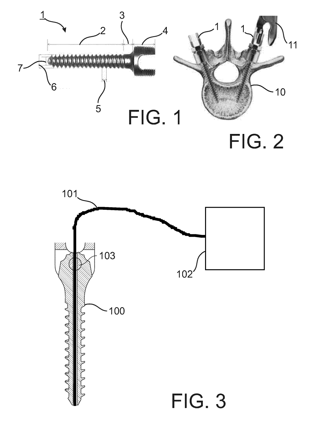
[0060]FIG. 1 shows a principle concept of a pedicle screw 1. The pedicle screw 1 includes a body 2, a neck 3 and a head 4. The body 2 is provided with a thread having a pitch 5, and outer diameter 6 and an inner diameter 7, such that the thread depth is the difference between the outer diameter 6 and the inner diameter 7.

[0061]FIG. 2 shows two pedicle screws 1 placed in a vertebra 10 together with a tool 11 for screwing the screw 1 into the bone.

[0062]As the skilled person is familiar with the general concepts of a pedicle screw as an example of an implantable device for being implanted into bone tissue and other such implantable devices for bone tissue, the tools already conventionally used in such context and the concepts of conventional placing the implantable devices into the bone tissue, further explanation thereof is not provided here.

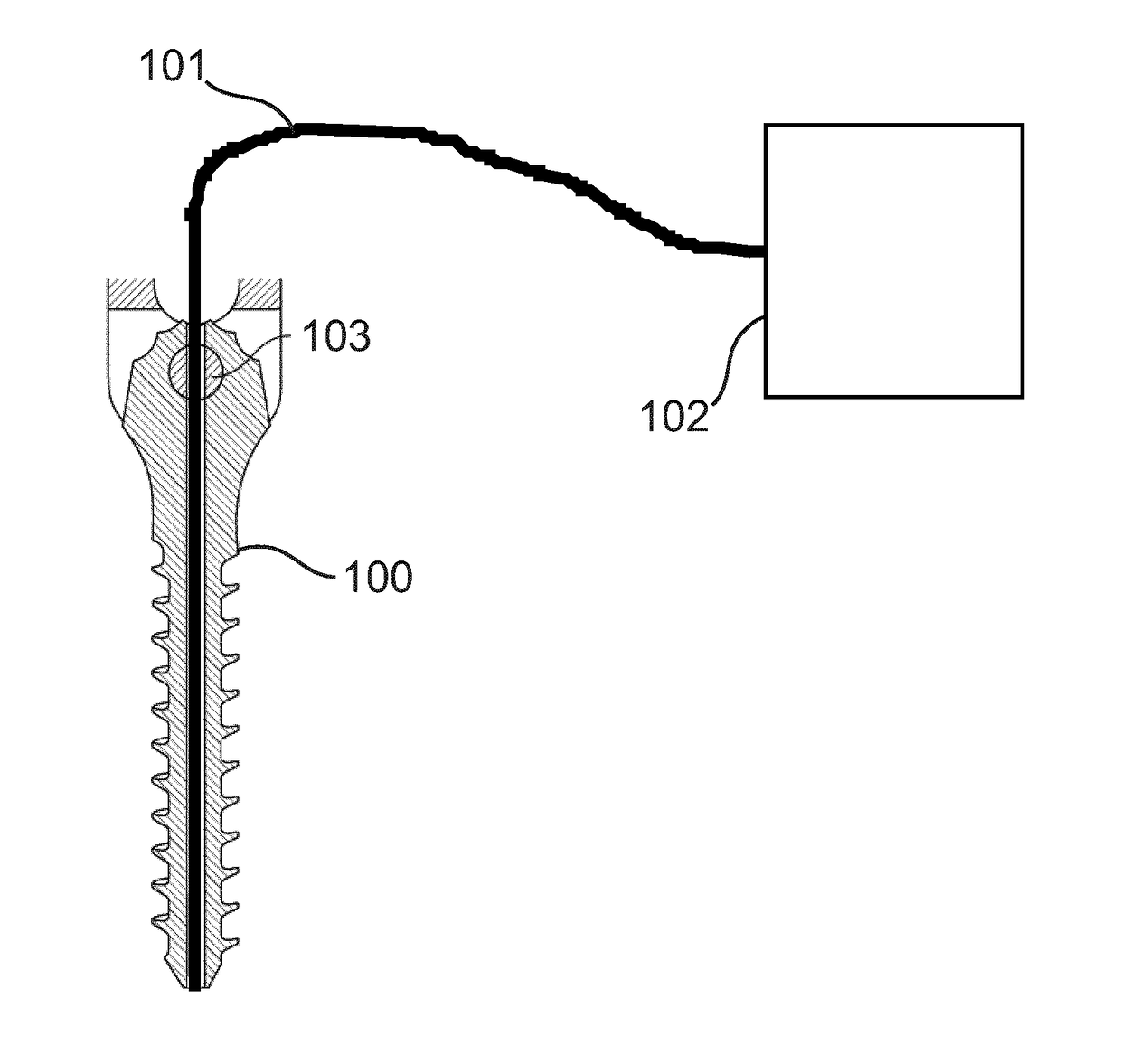
[0063]FIG. 3 shows a combination of a pedicle screw 100, an optical transmission device 101 and a processing unit 102 in accordance with an embo...


PUM


Abstract

The invention relates a system for implanting an implantable device in bone tissue, a processing unit for such system, a method of implanting an implantable device and a method of providing information for an implanting of an implantable device. In view of the finding that a fat content in cancellous bone is higher than a fat content in compact bone, the lipids fraction, which can be determined by optical means, e.g. spectroscopy, can be used to determine correct screw placement in healthy bone.

Description


Claims


Application Information

Patent Timeline
Owner KONINKLJIJKE PHILIPS NV
Why Eureka
Try Eureka