Multifunction structural furring system

a technology of structural furring and cladding panels, which is applied in the direction of covering/lining, construction, building components, etc., can solve the problems of limiting drainage and drying capacity, cladding system failure, and wind load rating of cladding panels fastened to conventional furring strips that may be less than desirabl

Active Publication Date: 2018-10-04
JAMES HARDIE TECH LTD
View PDF58 Cites 9 Cited by
  • Summary
  • Abstract
  • Description
  • Claims
  • Application Information

AI Technical Summary

Benefits of technology

[0005]The systems, methods, and devices described herein address one or more problems as described above and associated with current furring systems. The systems, methods and devices described herein have innovative aspects, no single one of which is indispensable or solely responsible for their desirable attributes. Without limiting the scope of the claims, the summary below describes some of the advantageous features.

Problems solved by technology

They typically must be installed in a vertical orientation so as to provide adequate drainage, as horizontally oriented furring strips can limit the drainage and drying capacity of a wall cavity behind a cladding.
In addition, the wind load rating on cladding panels fastened to conventional furring strips may be less than desirable.
Nail withdrawal or pull through are common causes of cladding system failure.

Method used


Image

  • Multifunction structural furring system
  • Multifunction structural furring system
  • Multifunction structural furring system

Examples


first embodiment

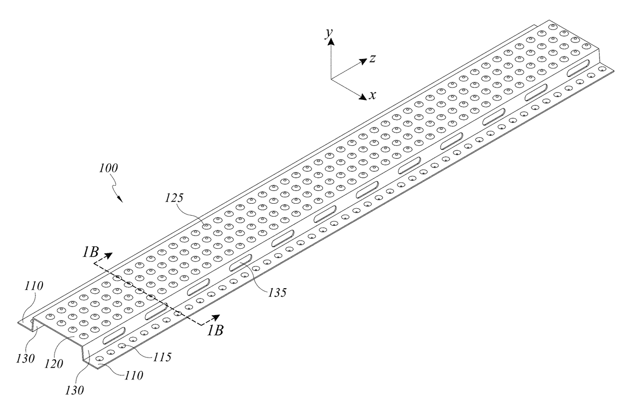
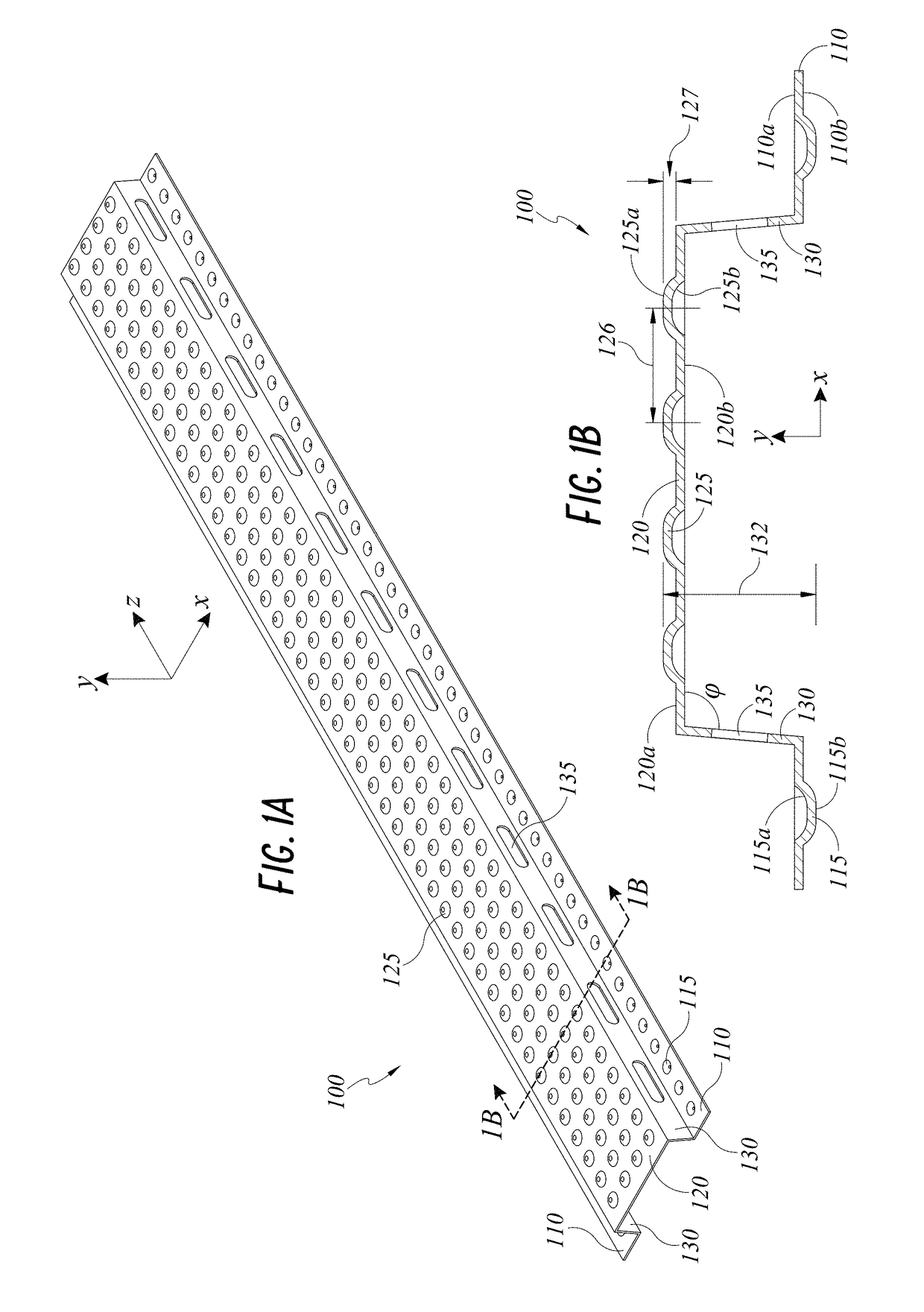
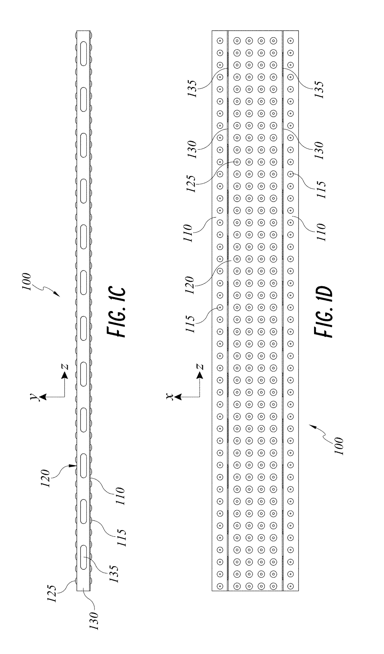
[0050]FIGS. 1A-1D depict a furring strip 100 incorporating drainage functionality. The furring strip 100 is a lineal structural member having a profile defined generally by legs 110, a face 120, and webs 130 disposed between and contiguous with the legs 110 and the face 120. The legs 110 are substantially planar and include leg dimples 115 spaced along the length of each leg 110. Similarly, the face 120 is substantially planar and parallel to the legs 110, with face dimples 125 spaced in an array along the length and width of the face 120. Webs 130 extend between the lateral ends of the face 120 and the medial ends of the legs 110, with web openings 135 spaced along the length of the webs 130. The dimples 115, 125, and web openings 135 provide enhanced drainage and ventilation, as will be described in greater detail below.

[0051]The furring strip 100 is configured to be installed adjacent to a building substrate to secure a cladding article, such as a fiber cement panel or the like, ...

second embodiment

[0057]Referring now to FIGS. 2A-2D, a furring strip 200 similarly comprises two legs 210, a face 220, and two webs 230 connecting the legs 210 and the face 220. The furring strip 200 is substantially similar in structure and function to the furring strip 100 depicted in FIGS. 1A-1D, including spaced leg dimples 215 and face dimples 225 arranged in an array of four rows. Unlike the furring strip 100 of FIGS. 1A-1D, the face dimples 225 of the furring strip 200 are arranged in a plurality of offset rows, wherein each row is displaced along the length of the furring strip 200, relative to each adjacent row, e.g., by 0.140625 inches (3.57 mm). As the lengthwise dimple spacing 226 of the face dimples 225 is 0.5625 inches (14.288 mm), the offset between adjacent rows results in a configuration in which no two face dimples 225 are centered on a line along the width of the furring strip 200.

[0058]Similar to the furring strip 100 of FIGS. 1A-1D, the furring strip 200 can comprise a metal suc...

third embodiment

[0059]FIGS. 3A-3D depict a furring strip 300 incorporating drainage functionality similar to the furring strips 100, 200 described above. The furring strip 300 includes legs 310, a face 320, and webs 330 connecting the legs 310 and the face 320. The face 320 includes face dimples 325 in a regular array configuration. Similar to the furring strip 100 of FIGS. 1A-1D, the face dimples 325 have a diameter of 0.3125 inches (7.938 mm) and are spaced along the length and width of the face 320 at 0.5625 inches (14.288 mm).

[0060]The furring strip 300 has a total height (as measured from the inner surface 310b of the legs 310 to the center of the protrusion 325a of the face dimples 325) of 0.375 inches (9.525 mm). The face dimples 325 have a height of 0.125 inches (3.175 mm). Due to the relatively shorter height of the webs 330 relative to the webs 130, 230 of FIGS. 1A-2D, web openings 335 of the furring strip 300 have a length of 1.125 inches (28.575 mm) and a height of 0.071 inches (1.8034 ...


PUM


Abstract

Structural furring systems having enhanced drainage functionality are described. Furring strips can include a substantially planar face, substantially planar webs extending from edges of the face, and substantially planar legs extending from opposite edges of the legs. The face and/or legs include a row or array of protrusions configured to accommodate drainage and ventilation between the furring strip and an attached exterior cladding and/or building substrate. Furring strips can be manufactured by rolling a sheet metal such as steel. Additional embodiments include a furring tape configured to be affixed to a substantially flat face of a commercially available furring strip to provide similar drainage features.

Description

CROSS-REFERENCE TO RELATED APPLICATIONS[0001]This application claims the benefit of priority under 35 U.S.C. § 119(e) of U.S. Provisional Application Ser. No. 62 / 478,980, filed Mar. 30, 2017, entitled “MULTIFUNCTION STRUCTURAL FURRING SYSTEM,” which is hereby incorporated by reference herein in its entirety.BACKGROUNDField[0002]The present disclosure generally relates to building construction materials and methods, and more particularly relates to cladding systems including furring.Description of the Related Art[0003]Cladding panels such as those made of fiber cement are frequently attached to the structural frame of a building to form a non-structural facade of the building. Furring strips are often disposed between the cladding panels and the building structure to form an air gap therebetween. The air gap creates a capillary break which allows for drainage and evaporation of moisture.[0004]Conventional furring strips can present a number of disadvantages. They typically must be in...

Claims


Application Information

Patent Timeline
Patent Type & Authority Applications(United States)
IPC IPC(8): E04F13/08E04F19/06E04F13/00E04B1/70E04B1/26
CPCE04F13/0805E04F19/06E04F13/007E04B1/7069E04B1/26E04F17/10E04F13/0887E04F13/0803
Inventor DIERCKS, CHADBATRES, BENJAMINMCENDREE, MICHAELSHAW, DAVIDGONZALEZ, JOSE
Owner JAMES HARDIE TECH LTD
Why Eureka
Try Eureka