LED projecting light fixture with additional light effects

a projecting light and light fixture technology, applied in lighting applications, lighting and heating apparatuses, instruments, etc., can solve the problems of not being able to use illumination purposes and midair effects, unable to provide zoetrope effects, and difficult to provide many light effects in projecting light devices

Active Publication Date: 2018-10-04
MARTIN PROFESSIONAL
View PDF4 Cites 8 Cited by
  • Summary
  • Abstract
  • Description
  • Claims
  • Application Information

AI Technical Summary

Benefits of technology

[0006]The objective of the present invention is to solve the limitations of the prior art described above and providing a compact projecting light fixture capable of creating a bright illumination and new light effects. This can be achieved by a projecting light fixture and method as defined by the independent claims. The benefits and advantages of the present invention are disclosed in the detailed description of the drawings illustrating the invention. The dependent claims define different embodiments of the invention.

Problems solved by technology

However it is difficult to provide a lighting apparatus with many effects as each kind of the light effect components take up space in the lighting apparatus.
Especially it is difficult to provide many light effects in projecting light devices as the light forming element need to be positioned in a focal point (the optical gate) of the optical system, and typical optical systems are only capable of focusing in a very limited area.
This Zoetrope system can only provide zoetrope effects and cannot be used for illumination purposes and midair effects.

Method used


Image

  • LED projecting light fixture with additional light effects
  • LED projecting light fixture with additional light effects
  • LED projecting light fixture with additional light effects

Examples


Embodiment Construction

[0006]The objective of the present invention is to solve the limitations of the prior art described above and providing a compact projecting light fixture capable of creating a bright illumination and new light effects. This can be achieved by a projecting light fixture and method as defined by the independent claims. The benefits and advantages of the present invention are disclosed in the detailed description of the drawings illustrating the invention. The dependent claims define different embodiments of the invention.

DESCRIPTION OF THE DRAWING

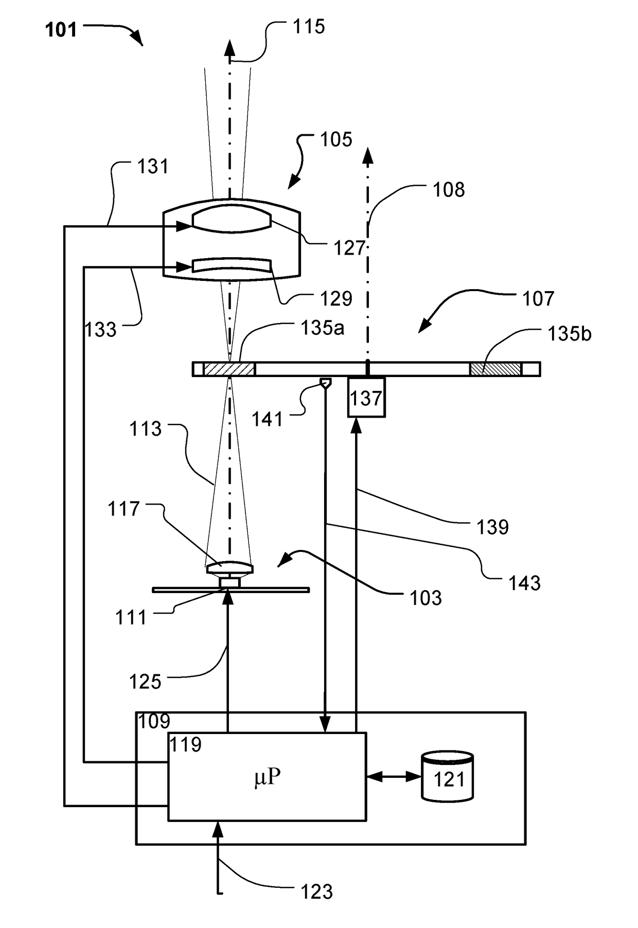
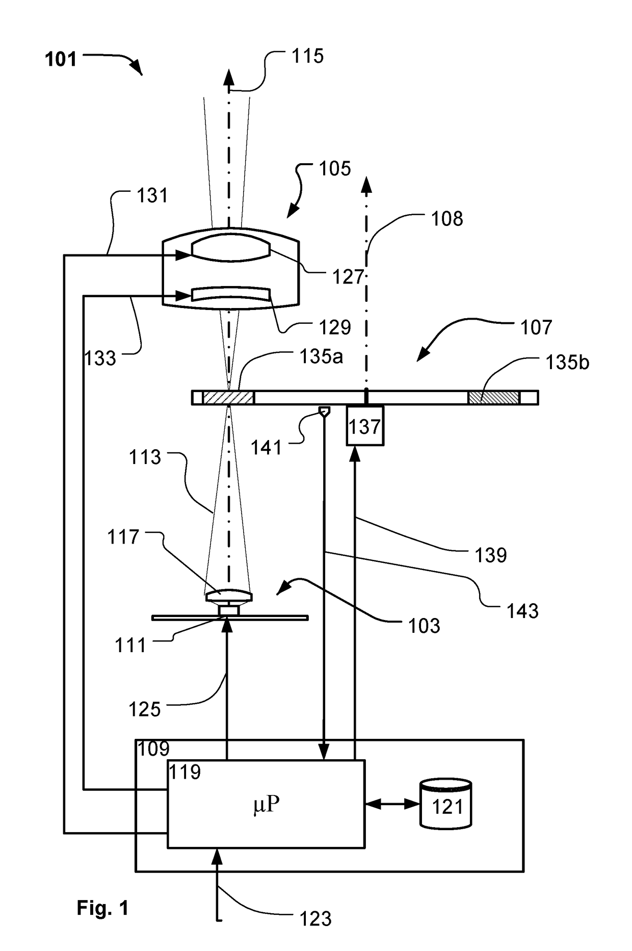
[0007]FIG. 1 illustrates a structural diagram a projecting light fixture according to the present invention;

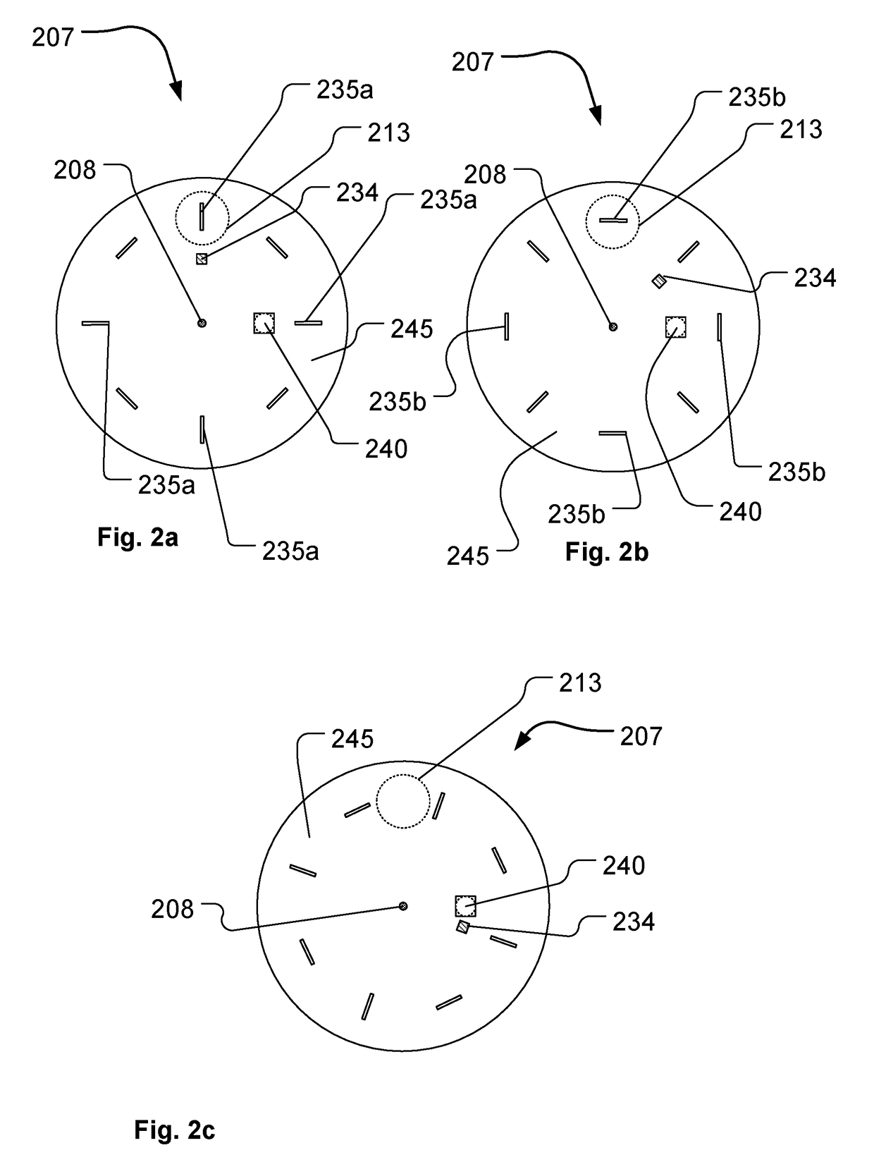
[0008]FIGS. 2a-2c illustrate different positions of a beam shaping object in relation to the source light beam in the projecting light fixture according to the present invention;

[0009]FIGS. 3a-3i illustrate different light patterns created by combining the different beam shaping patterns in FIG. 2a-2c;

[0010]FIGS. 4a-4c illustrate diff...


PUM


Abstract

The present invention relates to a projecting light fixture comprising at least one LED generating light beam and a projecting system positioned configured to project the light beam along an optical axis. A beam shaping object is arranged between the LED and the projecting system and comprises a least two different beam shaping patterns, which can be arranged in the source light beam upon rotation of the beam shaping object in relation to the light beam. An actuator is configured to continuously rotate the beam shaping object in relation to the source light beam in order to alternately arrange the beam shaping patterns in the light beam. The projecting light fixture comprises a synchronizer providing a synchronizing signal indicative of: the rotation speed and / or the angular position of the beam shaping object; the position of beam shaping patters in relation to the light beam. Where a controller is configured to toggle the LED between a LED on-period and a LED off-period based on the synchronizing signal.

Description

FIELD OF THE INVENTION[0001]The present invention relates to a LED projecting light fixture where an optical gate is illuminated by at least one LED and where a projecting system is configured to project the light passing through the optical gate along a primary optical axis. A beam shaping object is arranged near the optical gate and is configured to modify the light beam.BACKGROUND OF THE INVENTION[0002]In order to create various light effects and mood lighting in connection with concerts, live shows, TV shows, sport events or as a part of an architectural installation light fixtures creating various light effects are getting more and more used in the entertainment industry. Typically entertainment light fixtures creates a light beam having a beam width and a divergence and can for instance be wash / flood light fixtures creating a relatively wide light beam or it can be projecting fixtures configured to projecting images onto a target surface.[0003]Projecting light fixtures compris...

Claims


Application Information

Patent Timeline
Patent Type & Authority Applications(United States)
IPC IPC(8): F21S10/00F21V14/08F21V23/04F21V13/02
CPCF21S10/007F21V14/08F21V23/0407F21V13/02F21Y2115/10F21W2131/406G03B25/00G03B21/001F21V11/08
Inventor RASMUSSEN, NIELS JORGEN
Owner MARTIN PROFESSIONAL
Why Eureka
Try Eureka