Light emitting assembly, light bar, backlight module, display module and transparent display module

Active Publication Date: 2018-10-04
BOE TECH GRP CO LTD
View PDF5 Cites 3 Cited by
  • Summary
  • Abstract
  • Description
  • Claims
  • Application Information

AI Technical Summary

Benefits of technology

The patent is about a device that produces two types of light: first light and second light. The device has a reflector that reflects the first light to create a beam of reflected light that compensates for the second light. The technical effect of this invention is to produce a brighter and more complete light beam.

Problems solved by technology

Taking a LED which has an angle range of light emission of generally 120° for example, since the angle range of light emission of this LED is constant, application of a light bar having the LED is limited if it is used in the backlight source.
In the case of the angle range of light emission of the LED being 120°, since a critical light exit angle of light emitted by the LED is relatively larger and the display device cannot effectively utilize the light having such a large light exit angle, the whole display device has an extremely low light utilization ratio.
Moreover, a problem of one side of the display device close to the LED being brighter and the other side of the display device away from the LED being darker occurs due to the angle range of light emission of the LED, thereby the display device has a non-uniform brightness.
However, most LEDs are of constant light emission, therefore it cannot meet various application needs.

Method used


Image

  • Light emitting assembly, light bar, backlight module, display module and transparent display module
  • Light emitting assembly, light bar, backlight module, display module and transparent display module
  • Light emitting assembly, light bar, backlight module, display module and transparent display module

Examples


Embodiment Construction

[0038]The technical solutions described in the embodiments of the present disclosure will be clearly and completely described below with reference to the accompanying drawings in the embodiments of the present disclosure. It will be apparent that the described embodiments are merely part of the present disclosure and do not represent all the embodiments. All other embodiments obtained by those skilled in the art based on the embodiments of the present disclosure without creative work fall within the scope of the present disclosure.

[0039]Embodiments of the present disclosure are intended to provide a reflector, a light emitting assembly, a light bar, a backlight module and a display module, which can provide a light emission having an appropriate light performance according to the actual needs.

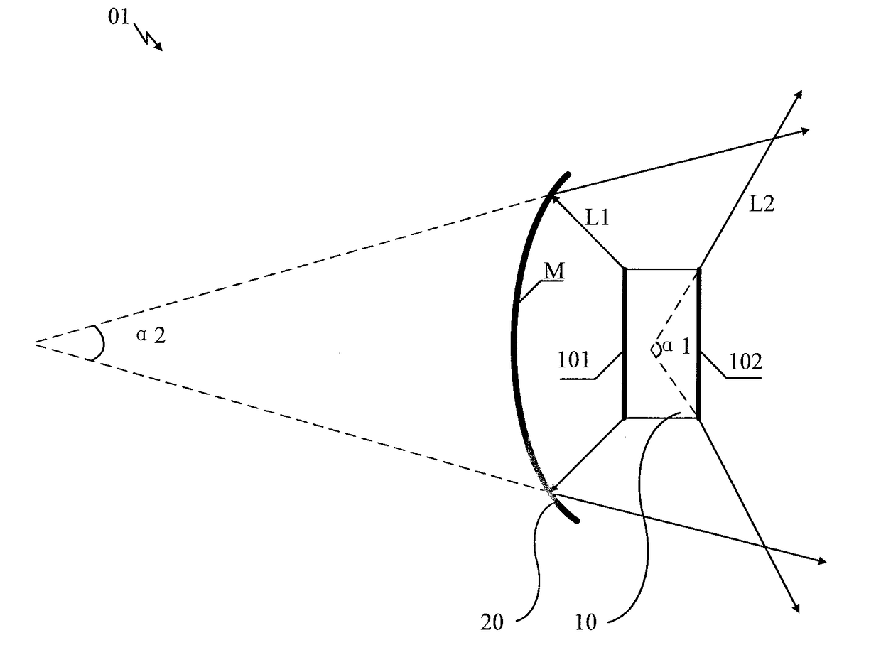
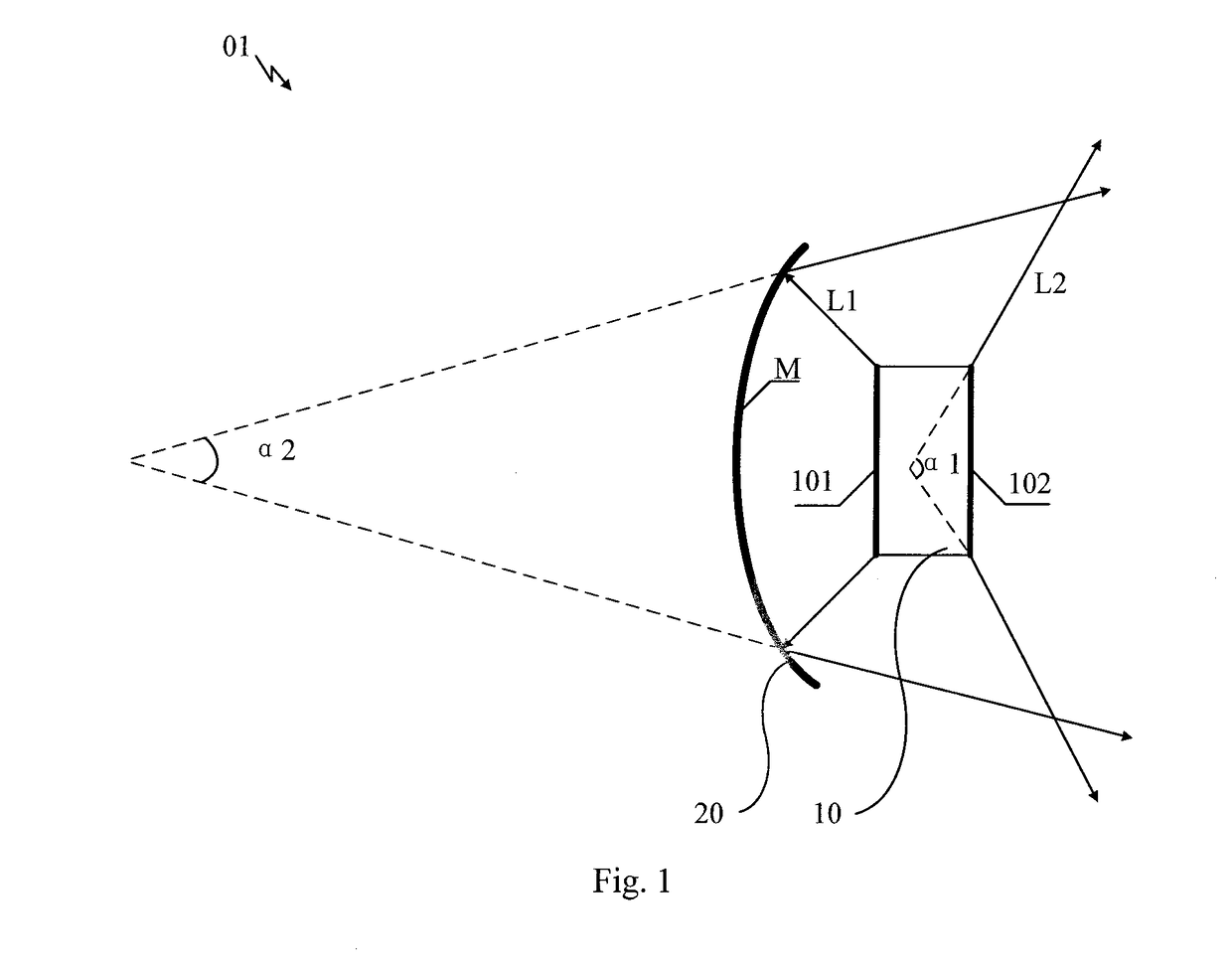
[0040]An embodiment of the present disclosure provides a reflector for use in a backlight source of a display device. As shown in FIG. 1, in a practical application, the reflector 20 is used in...


PUM


Abstract

Embodiments of the present disclosure provide a light emitting assembly, a light bar, a backlight module, a display module and a transparent display module. The light emitting assembly includes a light emitting body and a reflector provided at a side of the light emitting body. The light emitting body is configured to emit first light and second light, the reflector includes a reflective surface for reflecting the first light emitted by the light emitting body to form a reflected light beam, the reflected light beam compensating the second light emitted by the light emitting body. A direction of the first light is deviated from a direction of the second light, and each of the first light and the second light has a non-zero angle range.

Description

CROSS-REFERENCE TO RELATED APPLICATION[0001]This application claims the benefit of Chinese Patent Application No. 201710201756.6 filed on Mar. 29, 2017 in the State Intellectual Property Office of China, the disclosure of which is incorporated in entirety herein by reference.BACKGROUNDTechnical Field[0002]Embodiments of the present disclosure relate to a field of optical technology or a field of display technology, and more particularly, to a light emitting assembly, a light bar, a backlight module, a display module and a transparent display module.Description of the Related Art[0003]As flat panel display devices, liquid crystal displays (LCDs) have been more and more widely used in the field of high-performance display due to its characteristics such as small size, low power consumption, no radiation and relatively low production cost.[0004]As to the LCD, since liquid crystal itself cannot emit light, it is necessary to provide an external light source so as to achieve an image dis...

Claims


Application Information

Patent Timeline
IPC IPC(8): G02F1/1335
CPCG02F1/133603G02F1/133553G02F1/133526G02F1/133524G02F1/133605G02F1/133615G02B3/005G02B5/10G02B19/0028G02B19/0061G02B6/0031G02F1/13345
Inventor WANG, XINYANG, FANHAN, XUELINDU, JIANHUA
Owner BOE TECH GRP CO LTD
Why Eureka
Try Eureka