Air cleaner in two-stroke engine

Active Publication Date: 2013-02-28
MITSUBISHI HEAVY IND MEIKI ENGINES CO LTD
View PDF6 Cites 2 Cited by
  • Summary
  • Abstract
  • Description
  • Claims
  • Application Information

AI Technical Summary

Benefits of technology

The present invention is an air cleaner for two-stroke engines that employs a pivotable choke valve. This valve can open and close both the air passages and the air / fuel mixture passage simultaneously, making sure that the air enters the engine with high airtightness. The choke valve is designed to have a small angle range and work range, preventing the entire air cleaner from becoming too large. The valve has a flattened shape along its pivoting edge, making the operating angle smaller and reducing the work range. This allows the air from the closest air passage to be supplied smoothly into the air supply or the air / fuel mixture supply passage. The invention solves the problem of a large air cleaner by providing a pivotable choke valve that can achieve high airtightness, while also being highly maneuverable.

Problems solved by technology

However, providing separate choke valves for the respective inlets of the air passage and the air / fuel mixture passage will make the operating system of the choke valves complex because of the increased number of choke valves, and will increase the size of the entire device associated with the stratified scavenging two-stroke engine.
In such a stratified scavenging two-stroke engine, in addition to avoiding the operating system from becoming complex and the entire device from becoming large by using one choke valve as described above, high airtightness is required when the choke valve closes the openings.
However, with the technique disclosed in Patent Document 1, while high airtightness is achieved when the choke valve closes the openings as noted above, there is a problem that processing of the sealing surface for achieving the airtightness is difficult, since the sealing surface is large because of the use of the rotary valve member that has the rotation center positioned between the inlet openings of the two passages.
This will increase the size of the choke valve itself and its work range, which will in turn increase the size of the entire device.

Method used


Image

  • Air cleaner in two-stroke engine
  • Air cleaner in two-stroke engine
  • Air cleaner in two-stroke engine

Examples


embodiments

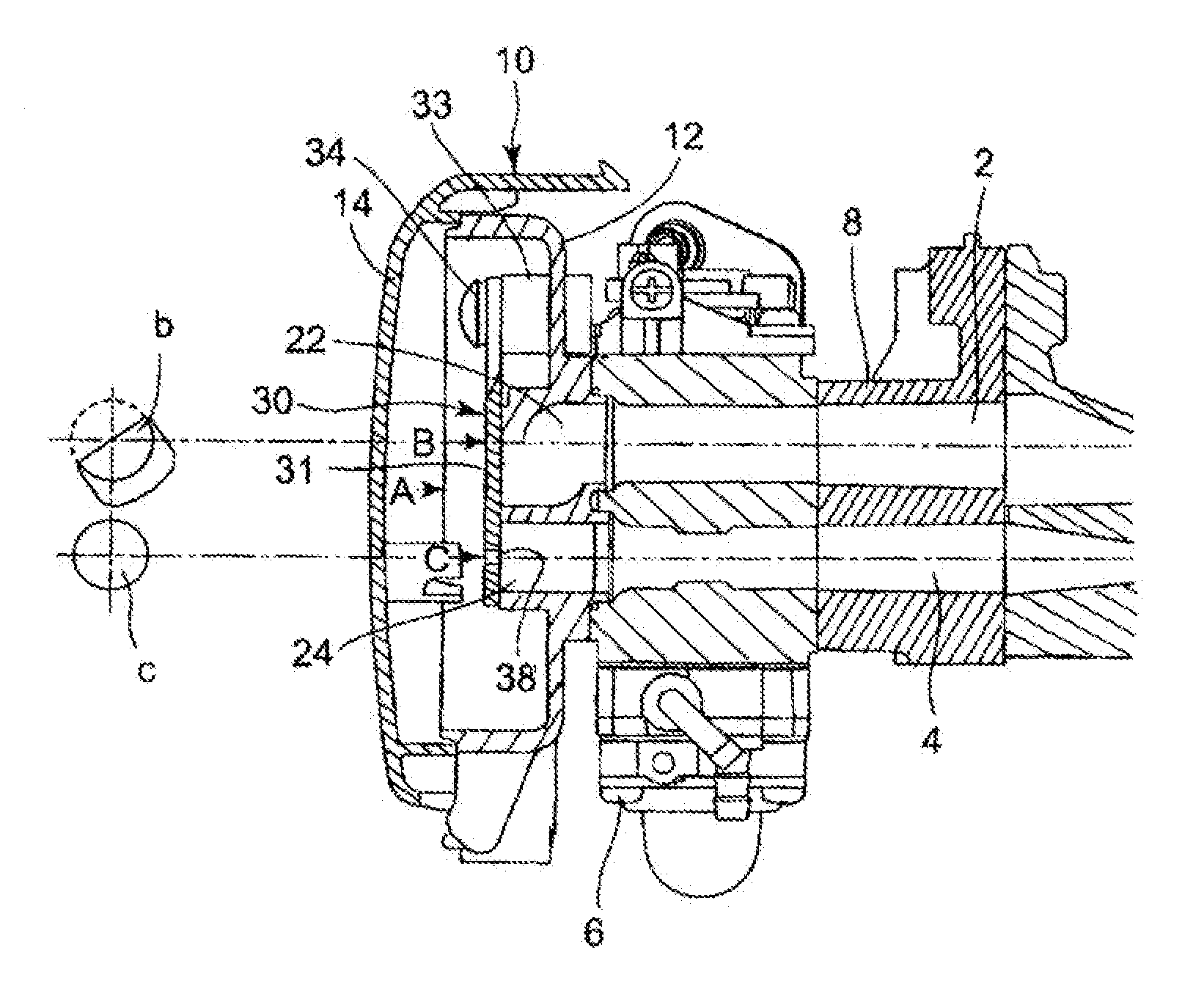
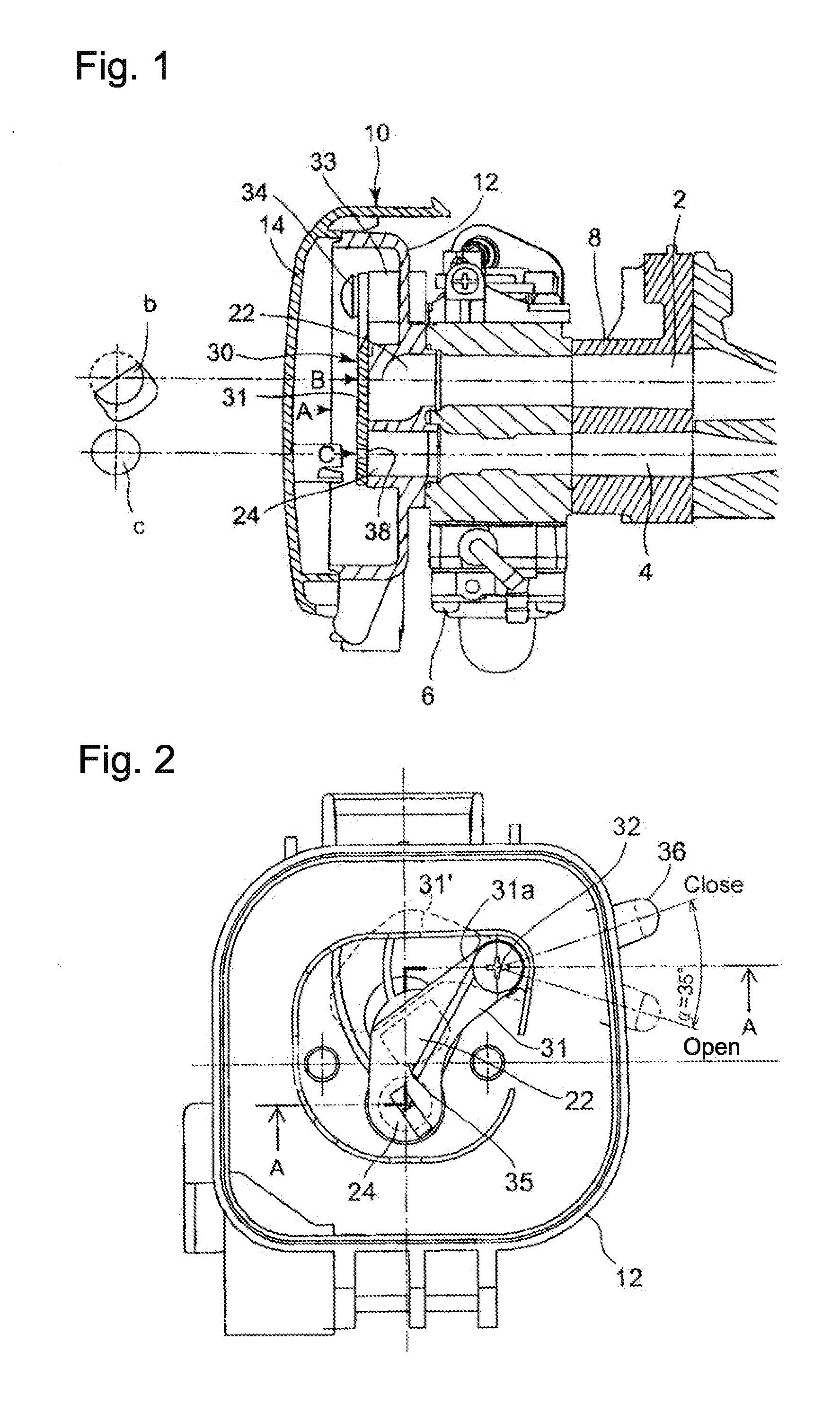
[0026]FIG. 1 is a structural view illustrating the structure of the vicinity of an air cleaner device for two-stroke engines according to one embodiment of the present invention.

[0027]In FIG. 1, reference numeral 6 denotes a carburetor, and 8 denotes an insulator interposed between the carburetor 6 and a cylinder (not shown).

[0028]Reference numeral 2 denotes an air supply passage, configured to communicate an air passage in the carburetor 6 via inside the insulator 8 with a scavenging port (not shown) opened in a side portion of the cylinder and a scavenging passage connected to the scavenging port. Reference numeral 4 denotes an air / fuel mixture supply passage, configured to communicate a throttle passage in the carburetor 6 via inside the insulator 8 and through inside the cylinder with a crank chamber.

[0029]Reference numeral 10 denotes an air cleaner, which is formed as described below.

[0030]Reference numeral 12 denotes a cleaner case, which is secured to the carburetor 6 with fa...


PUM


Abstract

An air cleaner in a two-stroke engine having an air supply passage and an air / fuel mixture supply passage includes: a first air passage and a second air passage arranged in parallel, the first air passage being communicated with the air supply passage and the second air passage being communicated with the air / fuel mixture supply passage; and a choke valve opening and closing both of the first air passage and the second air passage of the air cleaner. The choke valve has a pivot axis and a pivotable valve member pivoting about the pivot axis to open and close respective inlet openings of the first air passage and the second air passage. One of the first air passage and the second air passage that is located closer to the pivot axis has an inlet opening flattened along a pivoting edge of the valve member.

Description

TECHNICAL FIELD[0001]The present invention relates to an air cleaner structure in two-stroke engines, and more particularly to an air cleaner structure in a two-stroke engine having an air passage that is connected midway of a scavenging passage communicating a scavenging port with a crank chamber and that supplies leading air from the air cleaner to the scavenging passage, and an air / fuel mixture passage supplying air / fuel mixture created in a carburetor to the crank chamber.BACKGROUND ART[0002]A stratified scavenging two-stroke engine includes a scavenging passage communicating a scavenging port provided in a side portion of a cylinder with a crank chamber, an air passage connected midway of the scavenging passage for supplying scavenging air from an air cleaner to the scavenging passage, and an air / fuel mixture passage for supplying air / fuel mixture created in a carburetor to the crank chamber. Prior to supplying the air / fuel mixture from the scavenging port into the combustion c...

Claims


Application Information

Patent Timeline
IPC IPC(8): F02M35/04
CPCF02B25/22F02B2075/025F02M35/024F02M17/34F02M1/02
Inventor UENOYAMA, KAZUYUKIKIMURA, TAKAHIRO
Owner MITSUBISHI HEAVY IND MEIKI ENGINES CO LTD
Why Eureka
Try Eureka