Internally meshed transmission mechanism

a transmission mechanism and internal meshed technology, applied in the direction of gearing, gearing elements, hoisting equipments, etc., can solve the problems of large limited application of harmonic drive, and large volume of friction between the inner wheel and the roller, so as to reduce friction, reduce friction, and avoid interference

Inactive Publication Date: 2018-10-11
NINGBO HS POWER DRIVE TECH CO LTD
View PDF1 Cites 6 Cited by
  • Summary
  • Abstract
  • Description
  • Claims
  • Application Information

AI Technical Summary

Benefits of technology

[0058]Compared with the existing transmission system, the inner meshing transmission mechanism in accordance with the present invention can effectively avoid interference and reduce the friction coming from the engagement between the inner wheel and outer wheel, thus the gearbox or transmission system with the inner meshing transmission mechanism will have smaller size with larger speed ratio, larger output torque, longer life, higher efficiency and so on.

Problems solved by technology

However, when the tooth number difference is one (1) with traditional common involute gear for engagement, there is tooth engagement interference between the inner and outer gears, which will have tooth jam and consequently no rotation taken place between the inner and outer gears.
The application of harmonic drive is very limited because of the difficulty of flexspline manufacturing and small torque output.
However, the profile of fully closed cycloidal wheel is always engaging with the rollers on the outer wheel, which results in large volume of friction between the inner wheel and the rollers.
However, the size of transmission mechanism becomes larger and the rollers intent to be bended if large torque transmission is required because the rollers are supported on both ends but the force is loaded in the middle.

Method used


Image

  • Internally meshed transmission mechanism
  • Internally meshed transmission mechanism
  • Internally meshed transmission mechanism

Examples


Embodiment Construction

[0069]The following is the description of embodiments of the present invention with reference to the accompanying drawings. It shall be understood that all the terms for directional indication of parts and structure such as ‘front’, ‘rear’, up', ‘down’, ‘left’, ‘right’ etc. are used herein for convenience of explanation only. Since the disclosed embodiments of the present invention may have many different arrangements, such terms used for description shall not be regarded as a limitation to the invention. Wherever possible, the same or similar reference number for the parts or elements in different areas means the same or similar parts or elements.

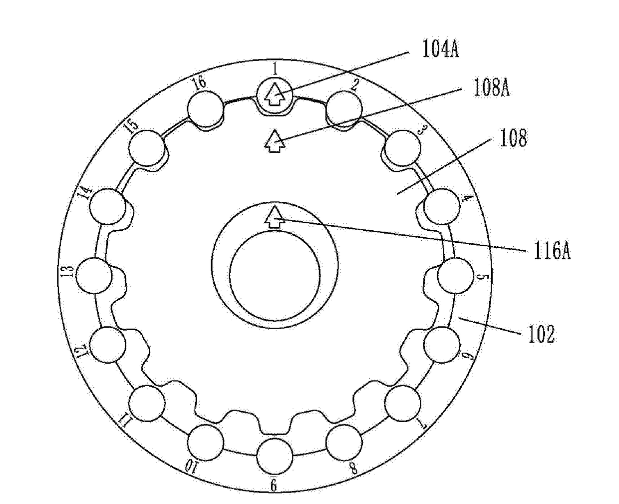
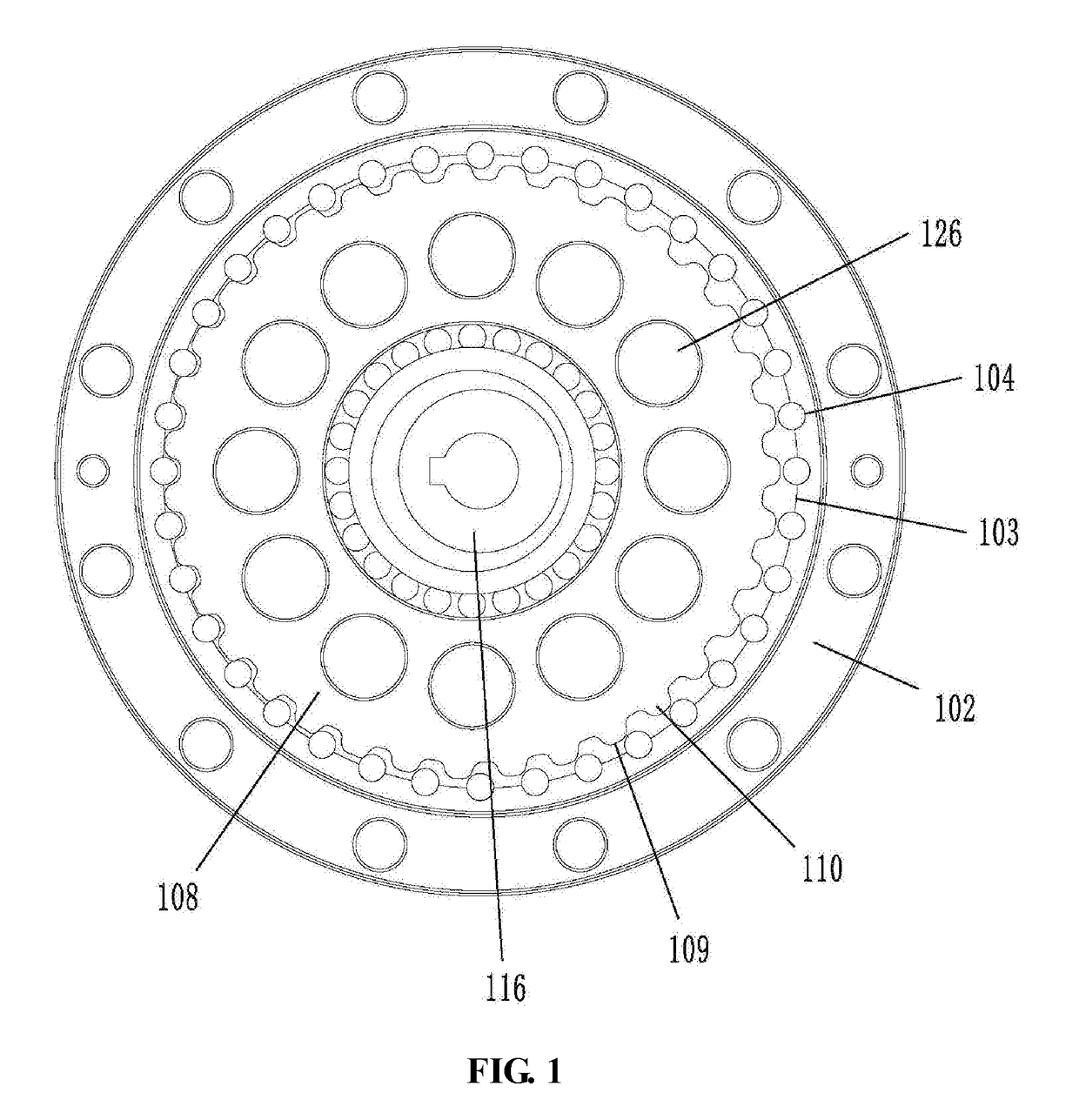
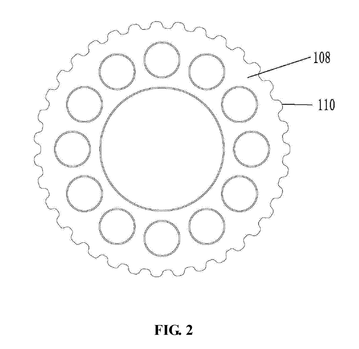
[0070]The inner meshing transmission mechanism according to the present invention as shown in FIG. 1 includes an outer wheel 102, an inner wheel 108 and an eccentric rotation device 116. The eccentric rotation device 116 is placed inside of the inner wheel 108 while the outer wheel 102 is placed outside the inner wheel 108. The inner meshi...


PUM


Abstract

The present invention provides an inner meshing transmission mechanism, which comprises an outer wheel, the outer wheel being provided with a first number of circular arc teeth on its inner edge, and said first number of circular arc teeth being arranged around the inner edge of the outer wheel; an inner wheel, the inner wheel being provided with a second number of teeth on its outer rim, said second number of teeth being arranged around the outer rim of the inner wheel, wherein m>n; an eccentric rotation device configured to enable said inner wheel to be eccentrically placed inside of outer wheel; wherein one of said outer wheel, said inner wheel and said eccentric rotation device is connected to an input power, while another one of them being connected to an output device so that power is transmitted through engagement between said outer wheel and said inner wheel; and wherein the toothed profile of said inner wheel is designed such that at any time when said inner wheel is engaging with said outer wheel for transmission, only a portion of said second number of teeth engage with said first number of circular arc teeth, while the rest of said second number of teeth are separate from said first number of arc teeth.

Description

TECHNICAL FILED[0001]The present invention relates generally to inner meshing transmission mechanism.BACKGROUND[0002]This section is intended to provide a background or context to the invention recited in the claims. The description herein may include concepts that could be pursued, but are not necessarily ones that have been previously conceived or pursued. Therefore, unless otherwise indicated herein, what is described in this section is not prior art to the description and claims in this application and is not admitted to be prior art by inclusion in this section.[0003]Compared with the external meshing transmission mechanism, the inner meshing transmission mechanism has better benefits such as smaller size, higher speed ratio of single-stage transmission, and easier to achieve multi-tooth meshing. For the inner meshing transmission mechanism, when the tooth number difference is one (1) between the inner and outer gears, the speed ratio is the largest. However, when the tooth num...

Claims


Application Information

Patent Timeline
Patent Type & Authority Applications(United States)
IPC IPC(8): F16H55/08F16H1/34
CPCF16H1/34F16H2001/323F16H2001/325F16H55/08F16H1/32F16H55/10F16H55/17F16H2055/176F16H2001/324F16H2055/0866F16H2055/0893
Inventor FAN, ZHENGFUCHEN, YUHAO
Owner NINGBO HS POWER DRIVE TECH CO LTD
Why Eureka
Try Eureka