Image generator and image generation method
a generator and image technology, applied in the field of image generator and image generation method, can solve the problem of paper waste and paper sheets, and achieve the effect of avoiding the waste of normal printed matter
- Summary
- Abstract
- Description
- Claims
- Application Information
AI Technical Summary
Benefits of technology
Problems solved by technology
Method used
Image
Examples
example 1
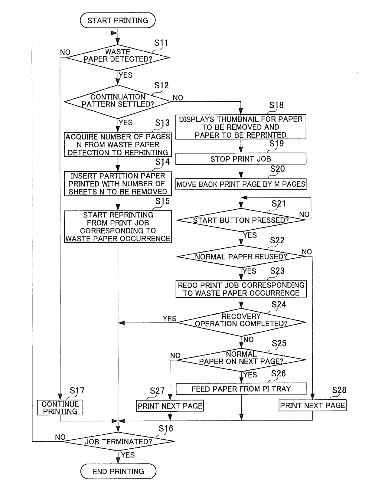
[0084]Example 1 provides a stop pattern example where the paper contiguous to or subsequent to the waste paper is normal-image paper (hereinafter also referred to as “normal paper”). FIG. 6 is an explanatory diagram illustrating handling operation of a stop pattern according to Example 1 when waste paper is detected. According to the example, the second paper P2 is detected as waste paper and three sheets of paper P3 through P5 subsequent to the waste paper are identified as normal paper. After the waste paper is detected, images on paper P3 through P5 are read to distinguish between normal paper (normal-image paper) and waste paper (paper printed with an abnormal image).
[0085]The number of sheets of paper output after detection of the waste paper, alternatively, the predetermined time / the number of pages from detection of the waste paper to the reprint (recovery operation), depends on the timing to detect the waste paper and a feed path distance from the paper container 20 or the p...
example 2
[0089]Example 2 provides a stop pattern example where waste paper and normal paper are mixed in the paper subsequent to the waste paper. FIG. 7 is an explanatory diagram illustrating handling operation of the stop pattern according to Example 2 when waste paper is detected. According to the example, the second paper P2 is detected as waste paper followed by three sheets of paper P3 through P5. The third paper P3 is identified as normal paper. The fourth paper P4 is identified as waste paper. The fifth paper P5 is identified as normal paper.
[0090]In Example 2, paper P2 is detected as the waste paper. Paper P3 is output as normal paper. Paper P4 is output as waste paper. Paper P5 is output as normal paper. Then, the print job stops. At this time, the manipulation indicator 91 displays a message indicating “remove paper P2 through P5 from the catch tray,” for example. In response to this message, the user removes waste paper P2 and subsequent paper P3 through P5 from the catch tray uni...
example 3
[0094]Similarly to Example 2, Example 3 provides a stop pattern example where waste paper and normal paper are mixed in the paper subsequent to the waste paper. FIG. 8 is an explanatory diagram illustrating handling operation of the stop pattern according to Example 3 when waste paper is detected. According to the example, the second paper P2 is also detected as waste paper followed by three sheets of paper P3 through P5. The third paper P3 is identified as normal paper. The fourth paper P4 is identified as waste paper. The fifth paper P5 is identified as normal paper.
[0095]In Example 3, paper P2 is detected as the waste paper. Paper P3 is output as normal paper. Paper P4 is output as waste paper. Paper P5 is output as normal paper. Then, the print job stops. At this time, the manipulation indicator 91 displays a message indicating “remove paper P2 through P5 from the catch tray and place paper P3 and P5 on the PI tray,” for example. In response to this message, the user removes was...
PUM
 Abstract
Description
Claims
Application Information
 - R&D
- Intellectual Property
- Life Sciences
- Materials
- Tech Scout
- Unparalleled Data Quality
- Higher Quality Content
- 60% Fewer Hallucinations
Browse by: Latest US Patents, China's latest patents, Technical Efficacy Thesaurus, Application Domain, Technology Topic, Popular Technical Reports.
© 2025 PatSnap. All rights reserved.Legal|Privacy policy|Modern Slavery Act Transparency Statement|Sitemap|About US| Contact US: help@patsnap.com


