Automatic pistol slide with laser

a laser and pistol technology, applied in the field of laser trainers, can solve the problems of dangerous and expensive conventional firearm training

Active Publication Date: 2018-11-22
CRIMSON TRACE
View PDF24 Cites 0 Cited by
  • Summary
  • Abstract
  • Description
  • Claims
  • Application Information

AI Technical Summary

Benefits of technology

[0004]In a preferred embodiment, when the pistol's trigger is pulled it causes the firing pin of the pistol to contact the striker and move the striker backwards away from its first position. This creates tension (preferably by expanding a spring) to move the striker forward when the firing pin disengages from the striker. The striker preferably has a portion that acts as a cam and eventually moves away from the firing pin as the striker is pulled back. When the firing pin moves away from and disengages the striker, the tension on the striker causes it to move forward past its first position to its second position. When in the second position it preferably contacts a switch, such as a momentary switch, that contacts the PCB and completes a circuit to send power from the power source to the laser. This causes the laser to emit light for a short duration, such as about 0.1 seconds, although any suitable duration may be utilized. After the striker moves to its second position, it moves back to its first position, preferably due to being biased by the spring, which is compressed when the striker is in its second position.
[0005]The slide may also include a trigger reset assembly, which would preferably be included in the housing. The trigger reset assembly applies force as the trigger is pulled. The force approximates or equals the normal force of pulling the trigger when using live ammunition. When the trigger is pulled and the firing pin is activated, the trigger reset assembly biases the trigger forward back to the trigger's reset position, so it can again be pulled without having to adjust the slide to reset the trigger.
[0007]A gun using the invention can hold a fully-loaded magazine, which helps target practicing with a gun having its normal weight when using live ammunition.

Problems solved by technology

Conventional firearm training can be dangerous, expensive (considering the prices for ammunition and replacement targets) and can only be performed in certain areas, such as shooting ranges.

Method used


Image

  • Automatic pistol slide with laser
  • Automatic pistol slide with laser
  • Automatic pistol slide with laser

Examples


Embodiment Construction

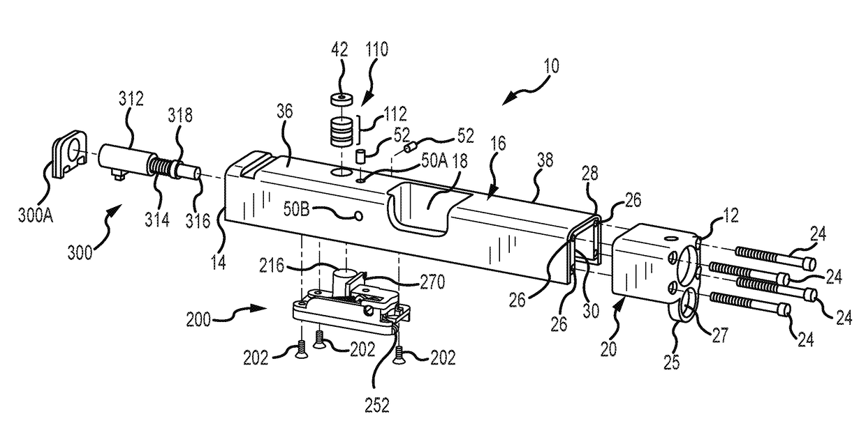
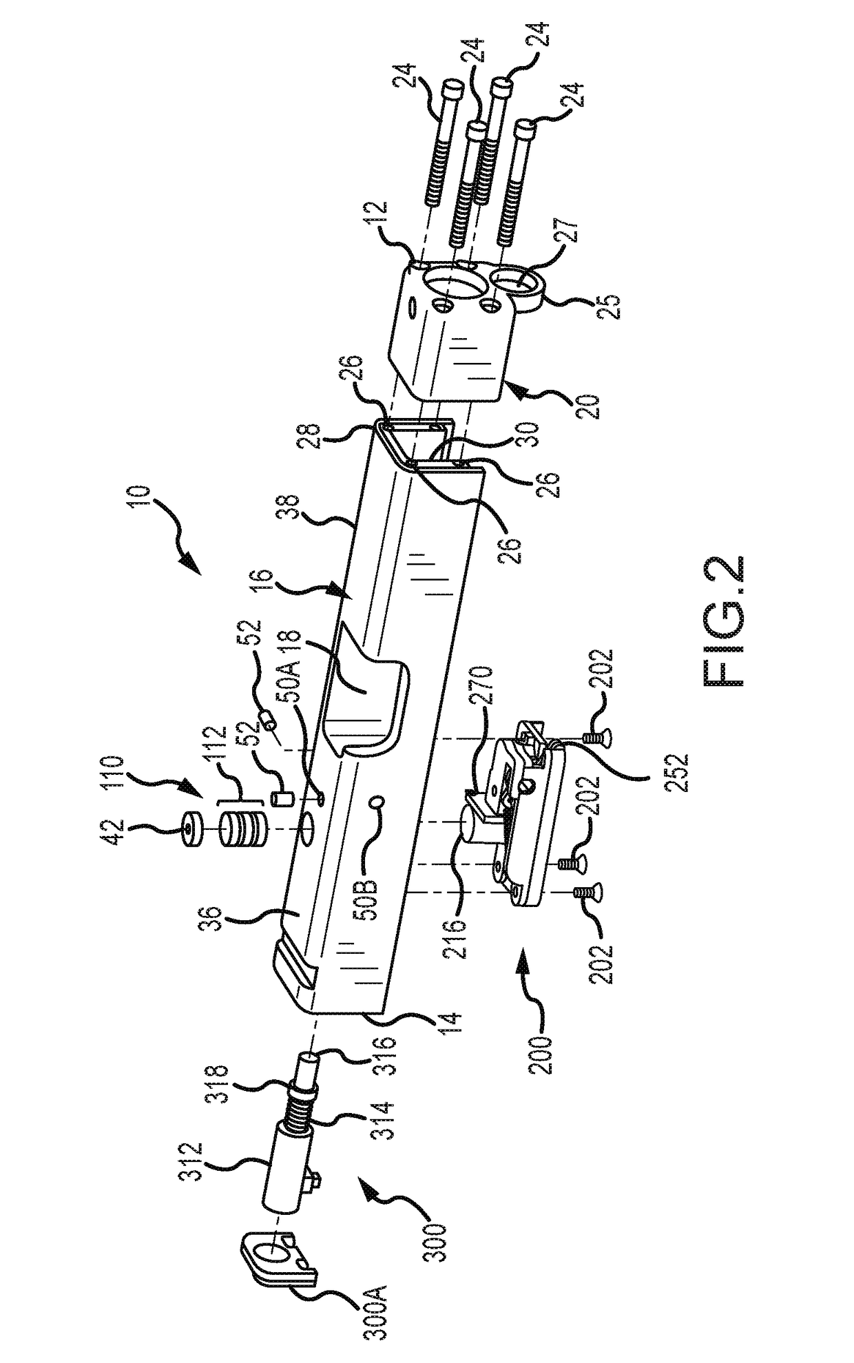
[0018]Turning now to the Figures, wherein the purpose is to describe preferred embodiments of the invention and not to limit same, FIG. 1 shows a slide 10 in accordance with aspects of the invention. Slide 10 has a first end 12, a second end 14, and a body 16. Body 16 has a partial cavity 18 to assist in gripping and moving slide 10. First end 12 is part of a nose assembly 20. Nose assembly 20 is interchangeable with other nose sections 60, 80, and 100, so slide 10 can fit different pistols, such as (for example) a Glock 17, a Glock 19, a Glock 21, or a Smith & Wesson 40 caliber automatic.

[0019]Nose assembly 20 has four openings 22 through which screws 24 pass and are threadingly received in openings 26 at an inner first end 28 of body 16. Nose assembly 20 also has a first opening 23 that aligns with the bore of the gun on which slide 10 is attached, and through which a bullet passes when fired if live ammunition is used. When slide 10 is on a gun, the gun cannot fire live ammunitio...


PUM


Abstract

A slide for an automatic pistol includes a cavity, a housing in the cavity, a laser module at least partially received in the housing, a power source, circuitry, and a striker. The slide has a first mode in which it emits laser light and a second mode in which it does not emit laser light. The striker has a first position in which it does not cause the laser module to emit laser light. When the pistol's trigger is pulled, the pistol's firing pin contacts the striker and moves the striker backwards from the first position to a biased position. When the firing pin moves out of contact with the striker, the striker moves forward to a second position and causes the circuitry to transmit power from the power source to the laser module, which causes the laser module to emit laser light.

Description

FIELD OF THE INVENTION[0001]The present invention relates to a laser trainer used with an automatic pistol having a slide.BACKGROUND OF THE INVENTION[0002]Conventional firearm training can be dangerous, expensive (considering the prices for ammunition and replacement targets) and can only be performed in certain areas, such as shooting ranges. The present invention allows firearm training to be performed safely, inexpensively, and almost anywhere without the use of live ammunition. Incorporated herein by reference is an exploded Figure of a Glock 17 Nomenclature Anglais / Francais and U.S. Pat. No. 9,170,079 entitled LASER TRAINER CARTRIDGE, to the extent these disclosures are not inconsistent with the disclosure in this application.SUMMARY OF THE INVENTION[0003]Aspects of the invention are directed to a slide that fits on an automatic pistol (or “pistol” or “gun”). Included as part of the slide is a housing in which a laser, printed circuit board (“PCB”) or other circuitry, and a pow...

Claims


Application Information

Patent Timeline
Patent Type & Authority Applications(United States)
IPC IPC(8): F41A33/02F41G1/35F41A19/35F41A3/12
CPCF41A33/02F41G1/35F41C3/00F41A3/12F41A19/35F41A3/54
Inventor MOORE, LARRY E.MOORE, AARON
Owner CRIMSON TRACE
Why Eureka
Try Eureka